Wiring Guide - TARS-AI-Community/TARS-AI GitHub Wiki
Wiring Guide for GPIO LCD Screen (if not using HDMI) and I2S Amplifier.
This section provides detailed instructions on how to wire an LCD display and an I2S amplifier to a Raspberry Pi, along with steps to calibrate the touchscreen and fine-tune the display. It assumes you are using an SPI-based LCD screen and an I2S amplifier for audio output.
LCD Wiring
To wire the LCD display to your Raspberry Pi, use the following pinout configuration:
| LCD Pin | Raspberry Pi GPIO Pin | Description |
|---|---|---|
| 1, 17 | 3.3V (Pin 1 or 17) | 3.3V power supply. |
| 2, 4 | 5V (Pin 2 or 4) | 5V power supply for the backlight (if required). |
| 6, 9, 14, 20, 25 | GND (Pin 6, 9, etc.) | Ground connections. |
| 11 | GPIO17 (Pin 11) | Touch IRQ (optional, for touch input). |
| 18 | GPIO24 (Pin 18) | LCD Register Select (DC/RS). |
| 19 | GPIO10 (Pin 19, SPI MOSI) | SPI MOSI (data sent to the LCD). |
| 21 | GPIO9 (Pin 21, SPI MISO) | SPI MISO (data received from touchscreen). |
| 22 | GPIO25 (Pin 22) | LCD Reset pin. |
| 23 | GPIO11 (Pin 23, SPI SCLK) | SPI Clock for LCD and touchscreen. |
| 24 | GPIO8 (Pin 24, SPI CE0) | SPI Chip Select for LCD. |
| 26 | GPIO7 (Pin 26, SPI CE1) | SPI Chip Select for touchscreen. |
Connecting the I2S Amplifier
For audio output, connect an I2S amplifier to the Raspberry Pi’s I2S (PCM) pins as follows:
| Raspberry Pi Pin | GPIO Pin | Function | Connect to Amplifier |
|---|---|---|---|
| Pin 12 | GPIO18 | I2S Bit Clock (BCLK) | BCLK |
| Pin 35 | GPIO19 | I2S Left/Right Clock (LRCLK) | LRCLK |
| Pin 40 | GPIO21 | I2S Data Out (DOUT) | DIN (Audio Data Input to Amplifier) |
| Pin 6 | GND | Ground | GND (Amplifier Ground) |
| Pin 2 or 4 | 5V | Power Supply | VIN (Amplifier Power Input) |
Note: Enable the I2S interface on the Raspberry Pi by following the instructions in the Adafruit MAX98357 guide.
Note: For a comprehensive layout of the Raspberry Pi 5’s GPIO pins, check out the detailed diagram here: 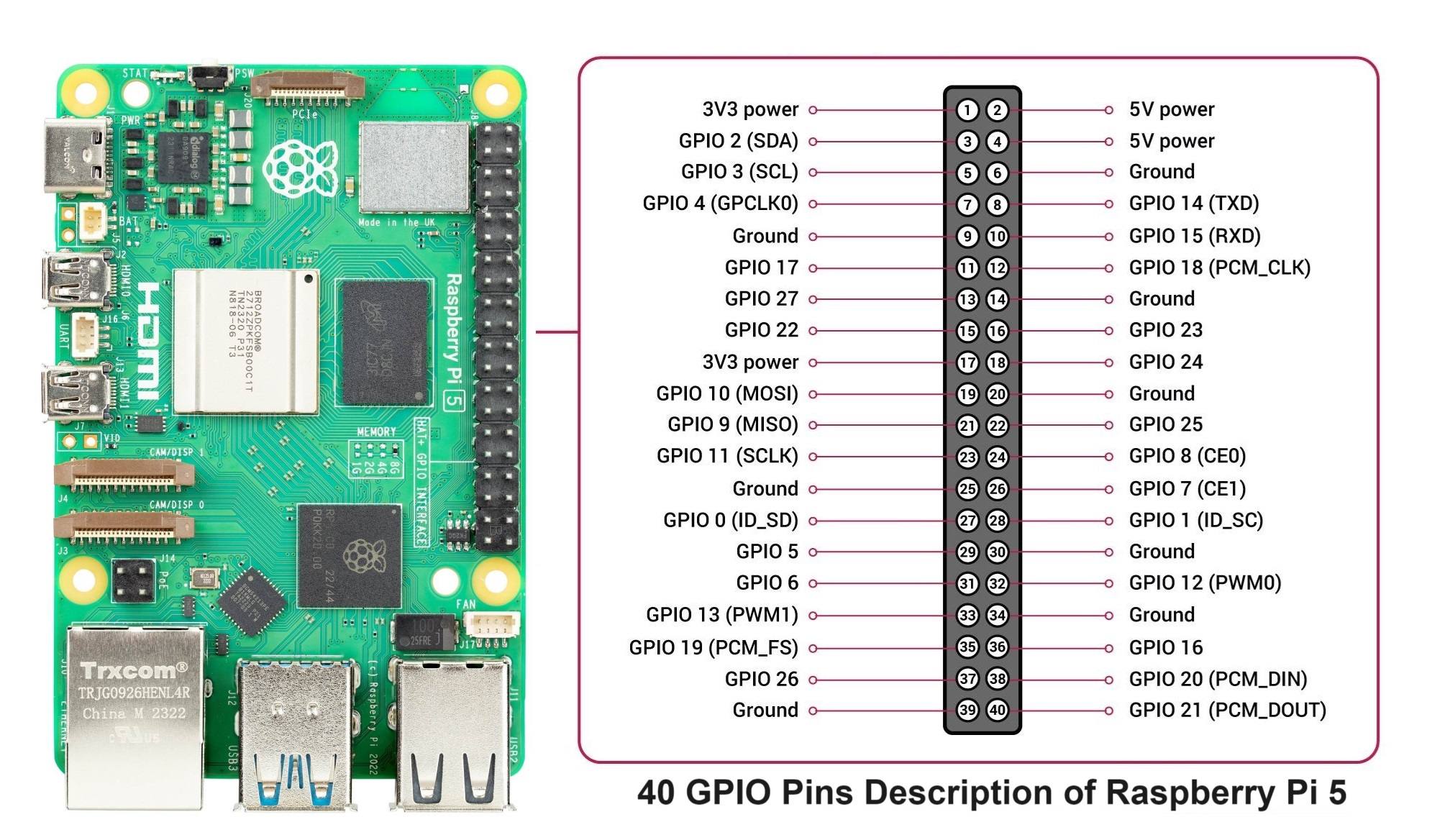
Connecting the 12CH PWM Servo Controller
| Controller Pin | Raspberry Pi GPIO Pin | Description |
|---|---|---|
| GND | GND (Pin 6, etc.) | Ground connection. |
| SCL | SCL (Pin 5) | Serial Clock Line for I2C communication. |
| SDA | SDA (Pin 3) | Serial Data Line for I2C communication. |
| VCC | 3.3V (Pin 1 or 17) | Power for the I2C logic. |
Note: Ensure I2C is enabled on your Raspberry Pi using raspi-config. If you need help setting that up, let me know!