L05 [Digital Logic II] - Skyline-9/CS2110-Notes GitHub Wiki
L05 [Digital Logic II]
Boolean Simplification Practice
Basically just put everything into this website: https://www.dcode.fr/boolean-expressions-calculator
Gray Code – only one switch per transition
000
001
011
010
110
111
101
100
The only version of Gray Code we need to remember is 2-bit
00
01
11
10
K-Maps
- Two adjacent 1s in the map means there is an x + x’ in the formula; the map tells us where
Strategy for 4-variable K-maps
- Find a box around 16 1's
- If so, you are done
- Find boxes around groups of 8 1's
- If no 1's are left, you are done
- Find boxes around groups of 4 1s
- If no 1s are left, you are done
- Find boxes around groups of 2 1s
- Find boxes around groups of 1
- Write a term for every box you drew
You can convert any of these to the other
- Truth table
- Circuit
- K-Maps
- Boolean expression
L05 [Digital Logic II]
Sequential Logic vs Cominational Logic
Combinational
- Combination of AND, OR, NOT (also NAND and NOR)
- Same inputs always produce same output
- Analogous to cheap bicycle lock
- Examples:
- XOR gate
- ALU
- Multiplexor
Sequential
- Requires storage elements
- Output depends on inputs plus state
- Analogous to a RLR combination lock
- Used to build memory & state machines
- Order matters
- Examples:
- R/S Latch
- Gated D Latch
- State Machine
- LC-3
- Register
Memory

Looking from the outside, we need
- Write enable
- Memory address
- In
- Out
Addressability is how many bits are in any one memory location
- The addressability of this memory is 8 (8 bits for in and out)
Address space is 4
From the slides, the official definitions are
Address Space -- How many addresses are possible?
Addressability -- How big is each memory location?
Memory Space
Equation: Memory = Address Space * Addressability
- Remember that address space is 2^bits
Basic Building Blocks of Memory
- Register
- Gated D Latch
- Decoder
- Multiplexor
Sequential vs Combinational Logic Circuits
Combinational Logic Circuits
- Make decisions
- Same inputs always produce same output
- Depends on what is happening now
Sequential Logic Circuits
- Make decisions and store information
- Output depends on inputs AND state (can make state machine)
- Depends on what has happened in the past (state) as well as what is happening now

A Wrinkle With the D Latch
Problem
A Gated D Latch is a level-triggered device, that is, it will store whatever value is present on the input when the write enable goes from true to false
First, let's introduce what a clock is. A clock is an electrical signal that oscillates between high and low voltage (square waves of 0 and 1). Connect to write-enable of the D-latch to record.
When the clock signal is at its top, the register will output its current inputs. Similarly, when the clock signal goes to zero, the register will record its inputs.
Basically when clock goes to 1, write enable turns on.
When the clock is low

The register is locked when the clock is low, so 7 is passed through the register
When the clock is high

When the clock is high, the register will pass through the values, so 12 will be passed through the register. Problem: we get unexpected results if the output of the device is used in computing the input to the same device
Leader-Follower Flip Flop
Also called a Master/Slave flip flop


Instead of using Gated D-Latches, you would use leader-follower flip flops (d-flip flop or register in Circuitsim)
9/14/2021 Attendance Quiz
Today's Number: 82,200
Question #1: Level-triggered sequential circuits can yield unexpected results if
D. The output of the device is used in computing the input to the same device
The improvement is edge-triggered (locked on the clock edges instead of the level dropping). Remember level-trigger is just a regular D-latch
Question #2: How many bits of storage are we going to need for the garage door opener state machine?
3
Question #3: With three inputs and three state bits, how many lines would the truth table require if it didn't contain "don't care" entries?
64
Finite State Machine
With combinational logic and sequential logic (storage elements), we can start building finite state machines
Example
We have a button that we want to open and close the garage door when we press the button. More specifically,
- When the garage door is down and we press the button, we open the door
- When the garage door is up and we press the button, we close the door
Note: every time you make a clock tick, you have to transition to a state, even if you transition to yourself
What keeps you in the same state? What happens if you just hold down the pushbutton?
To solve this, we introduce a dummy state when the button is held down

There are two types of state machines
| One Hot | Binary Encoded |
|---|---|
| One bit per state | Encode state as a binary number |
| Only one bit is on at a time | Use a decoder to generate a line for each state |
| Faster | Slower |
| Requires more flip-flops | More complicated |
| 00001»00010»00100»01000»10000 | 000»001»010»011»100 |
L06 [Von Neumann Model]
Harvard Model
They stored data and programs separately
Von Neumann

- Stored data and program together in the same memory
Pros
- Less circuits
Cons
- Can mix up data and program
- Program can change all the program data as well
The Von Neumann model leads us to treat machine instructions just as another data representation
- Big deal!!
Think of
- Unsigned integers
- IEEE-754 floating point numbers
- ...
- Machine Instructions
They are all just bits!
Introducing the LC-3 CPU
| Address Space | Addressability | Architecture | General purpose registers | Instruction size |
|---|---|---|---|---|
2^16 = 65536 |
16 bits |
Von Neumann | 8 |
16 |
Address space for modern 64-bit computers is 2^64, though in practice the memory is limited by the CPU, the memory controller, or the printed circuit board design
Series of 16-bit numbers becomes your program instructions! Yay :D

- The slashes on the wires just means how many wires are chained together
Tri-state buffer
The tri-state buffers are used to help with the bus
- The bus is 16 shared wires in the datapath
- This is what is used to disconnect inputs so the bus can be shared among multiple components
A triangle is just a buffer
- Add a bubble and it becomes a not gate
- Buffer by itself does nothing, 1 goes in 1 goes out and 0 goes in and 0 goes out
Patt names all his tri-state buffers with the prefix “gate”
Remember – our logic gates literally connect their output to +VCC for 1 and Ground for 0
- When sharing a wire with another circuit – this arrangement is called a bus
- What happens when you connect a 1 (+VCC) to a 0 (ground)? You short circuit

Z means floating high impedance (wire is basically cut off, we don't know the voltage)
Tri-state buffers are bit more complicated than transitors because you have to pass both a 1 and a 0 to the output
If my address space is 8, I need 3 wires (2^3)
Register File Circuit
- A small, fast "Memory"
- Address space: 8 registers
- 16-bit addressability per reg
- The single /16 on the top represents data in
- Two outputs
- Dual ported memory
- Can read two regs at same time
- Source Register 1 (SR1) [3 bit address]
- Source Register 2 (SR2) [3 bit address]
- One input
- DR (3 bit address)
- Chooses which register to write into
- LD.REG (write enable)
- DR (3 bit address)
Property of Leader-follower flip-flop: you can read a value in and write a value out at the same time

Categories of Machine Instructions
Operate (ALU)
- ADD
- AND
- NOT
Data Movement
- Load
- LD
- LDR
- LDI
- LEA
- Store
- ST
- STR
- STI
Control
- BR
- JMP
- JSR
- JSRR
- RET
- RTI
- TRAP
How do we make the LC-3 do an “ADD”?
The LC-3 is controlled by a large finite state machine.
So it has output signals (control signals)
- Like UP and DOWN signals in the garage door
The FSM turns on specific control signals in the LC-3
- This activates certain paths in the datapath.
- These control signals can make the datapath do things, such as add two numbers (R1 and R3), and store the result in R2.
Participation Quiz 9/16/2021
Today's number is 30,900
- Tri-state buffers are used to
- Prevent data path fires
- Avoid short circuits
- Disconnect a circuit from a bus so that another circuit can assert a value on the same bus without interference
- Present a value that is neither a 1 or 0 on an output
- The Program Counter (PC) register holds
The address of the next instruction to be executed
- The Instruction Register (IR) holds
The instruction currently being executed
Recitation 9/15
Sequential Logic
Output depends on previous output and input
R/S Latch (Reset/Set Latch)
- Stores one bit
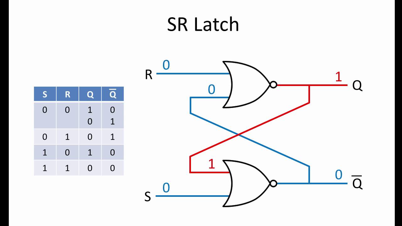
| R | S | Out | !Out |
|---|---|---|---|
| 0 | 0 | X | X |
| 0 | 1 | 0 | 1 |
| 1 | 0 | 1 | 0 |
| 1 | 1 | 0 | 0 |
When at R = 1, S = 1, the output at this state depends on the previous state (moldy state)
Gated D-Latch
Gated D-Latches are basically just an RS-Latch with extra control
- Can choose when to save the output and what to save it as
Level-triggered Logic
- In level-triggered logic, the output can only change when the enable bit is 1
- When the enable bit is set to 0, then the output is unaffected by changes in the input
Edge-Triggered Logic
- Rising-edge triggered logic: The output can only change when the clock changes from 0 to 1
- Falling-edge triggered logic: The output can only change when the clock changes from 1 to 0

D-Flip Flops
- Left D-latch updates when the clock is 0, and the right D-latch updates when it is 1

It's kinda like an air lock for a space station
- To get out, you open the air lock, close it, then open the outer door
- To get in, open the outer door, close the outer door, then open the air lock
Registers
Register just links together a bunch of d-flip flops and syncs them to the same flop
- Essentially the same as a D Flip-Flop, but there are n-bit input or output lines instead of just one
State Machines
Dave has 3 possible states
- Dancing (requires 3 charges)
- Charging with 1 charge
- Charging with 2 charges
![]()
Address Space & Addressability
Computer memory is made up of distinct memory addresses, each containing some amount of data
Addressability: the amount of data stored at any given memory address
Address space: An n-bit address line can represent 2n memory addresses