Amplifier - SA5NNN/VLF-Receiver GitHub Wiki
The first amplifier is the one giving us real amplification of the signal from the resonant circuit. It is based on a MOSFET and looks like this:
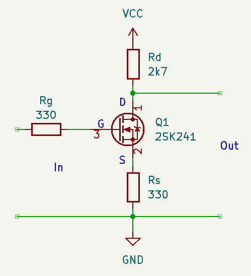
Figure1
This circuit is known as common source amplifier. The specific one that Paul uses has a couple of extra features such as source degeneration and oscillation protection. The full schematics in the radio shows also decoupling and DC block capacitors, those are removed here so we can see the forrest despite the trees.
MOSFET signal input is on the gate, and the gate is isolated on the substrate, you can expect several GOhm of resistance! Therefore we have a gate current of 0. The BJT relies on current amplification, but MOSFET has no current in, so relies on voltage amplification.
$R_g$ is the gate resistor, $R_d$ the drain resistor and $R_s$ the source resistor.
$R_s$ is not always used in the circuit. It's often called swamping resistor and it helps stabilize the gain and reduce distortion, at the expense of some gain. $R_g$ is the resistance seen from the input, if self bias, combination bias, zero bias and constant current bias, this will be the single biasing resistor $R_g$. If biased with a voltage divider, it is the two divider resistors in parallel.
We have the following values for small signals at low frequencies:
Voltage gain: $A_V = - \frac{g_m R_d}{1+g_m R_s}$ where $g_m$ is the transconductance or transfer admittance (Y), the change in output current caused by a certain change in input voltage.
If not swamped: $A_V = -g_m R_d$
Unloaded input inpedance: $Z_{in} = R_g \parallel R_{GS} \approx R_g$ since $R_{GS}$, the input resistance is very large ($10^12$)
Unloaded output inpedance: $Z_{out} = R_d$
An example
Lets consider Pauls construction where non-essential components are removed for simplicity:

Figure 2
Before using the gain formula, we need to find a value for the transconductance $g_m$. We use the datasheet for this, and