Nano V3 Ethernet Shield W5500 — Connection - RobotDynOfficial/Documentation GitHub Wiki
Nano V3 Ethernet Shield W5500 connects to the controller RobotDyn Nano V3 by a simple “sandwich” connection, as the pinout of both boards is the compatible. The main number of GPIO contacts of the Nano controller passes through the shield, not used by it at all and remains available for connection of various peripherals like sensors, actuators, etc.

***Warning. Pay attention to the wiring and the correct connection of the shield and the microcontroller board, otherwise the board and shield may fail. ***
Some contacts are used jointly by both the shield and controller boards, and their purpose will be described in more detail below.
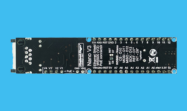
The diagram below shows the pinout of the board Nano V3 Ethernet Shield W5500. Connectors for the optional PoE module are listed separately. In this diagram, all the contacts that are used for communication between boards Nano V3 Ethernet Shield W5500 and Nano V3 are marked. Those contacts that are not marked in a special way remain free for you to connect and use as a GPIO in your projects.

SPI interface is used for communication between the controller and the shield and controls the operation of the network shield by the microcontroller. Contacts D10, D11, D12, D13 are used by the shield and cannot be used as GPIO for any other needs.
D10/CS - device selection contact on the SPI interface bus D11/MOSI - MOSI pin of the SPI interface D12/MISO - MISO pin of the SPI interface D13/SCK - SCI pin of the SPI interface
For advanced users and professionals who need more control over the equipment, RobotDyn engineers on the shield board have jumpers for connecting them by soldering. By closing and opening these contacts, you can control the operation of additional functions of the network controller.
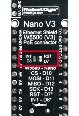
Jumper RST - D7
Initialization of the WIZnet W5500 chip. Default state: closed. The W5500 chip is initialized by connecting a high level to an RST pin. If you want turn on/off of the Ethernet module (for example, to reduce the power consumption of the system or disconnect the network at the hardware level), you can remove the jumper D7 and independently control the W5500 chip.
In this case, add the initialization lines of the RST pin to the sketch code and set high potential on it:
#define RST 7 // W5500 RST

// If you want to control Reset function of W5500 Ethernet controller
pinMode(RST, OUTPUT);
digitalWrite(RST, HIGH);
If you set a low potential on the RST pin, this will stop the W5500 chip and, accordingly, disable the Ethernet of your device.
digitalWrite(RST, LOW);Jumper INT - D8 Receiving an interrupt signal from the W5500 chip. Default state: ** open **. By closing this jumper, you get the opportunity to use the interrupt signal from the W5500 chip. If this pin is high, then the W5500 chip is receiving Ethernet data at this point. This feature can be used in advanced network operation scenarios of the controller.
The Nano V3 Ethernet Shield W5500 board also has two special pinouts for an optional PoE module.
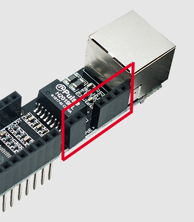
You just need to connect the PoE module to the Nano V3 Ethernet Shield W5500 board and you can disconnect your system from the network adapter - power will be supplied through an Ethernet cable (for this, the Ethernet cable itself must be connected to equipment supporting the PoE standard).
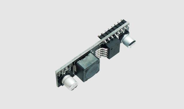
The figure below shows the view of the PoE module designed to connect to the Nano V3 Ethernet Shield W5500 shield.
View of both the Nano V3 Ethernet Shield W5500 boards and the PoE module assembly:

V1 - PoE power pin 1 V2 - PoE pin 2 V3 - PoE pin 3 V4 - PoE pin 4 power
VIN - contact of the output voltage of the PoE module GND - ground
| Value | Value |
|---|---|
| Input Voltage (Vin) | 7 / ~ 12V |
| PoE Type | No PoE / Active PoE / Passive PoE |
| Power IN (PoE) | Optional module, 48V (input), 9V (output) |
| Ethernet socket | RJ45 |
| PCB Size | 17.8x77.0 mm |
| Weight | 15g/25g (with PoE module) |
| Value | Value |
|---|---|
| Ethernet Power (IN) | 12 / ~ 48V DC |
| Output | DC 9V |
| Value | Value |
|---|---|
| Ethernet Power (IN) | 12 / ~ 48V DC |
| Output | DC 12V |
The board Nano V3 Ethernet Shield W5500 has small overall dimensions 17.8x77mm and light weight: 15 grams without a PoE module and 25 grams complete with a PoE module.
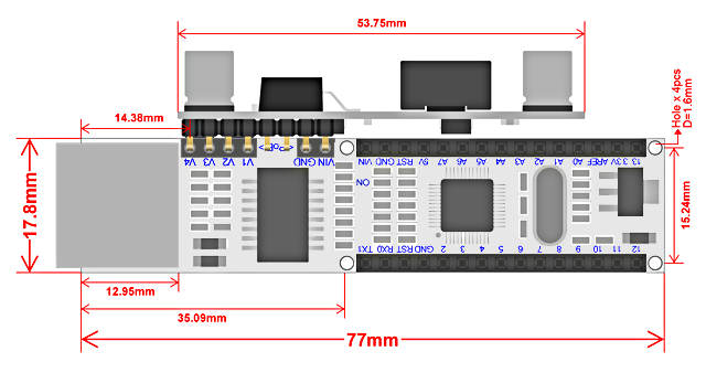
The figure below shows the circuit diagram of the board Nano V3 Ethernet Shield W5500 and the PoE module connected to it. You can use this diagram to clarify details and better understand the operation of the Nano V3 Ethernet Shield W5500 shield.
