Camera_Models - RicoJia/notes GitHub Wiki
========================================================================
========================================================================
-
Lens Model
-
Pin Hole Model
-
we need a small hole to "confine" lights into a single source. Otherwise light from different sources might be casted on the same spots.
caption
Pin Hole provides a Point Light Source
-
image is upside down
Two models
-
-
Diffraction: 2 types - when you have an object large enough, or a slit small enough
Small Slit will Produce Diffraction
Diffraction is a wave will change its direction
-
The Pinhole shouldn't be too big (too much light come in), or too small (diffraction, so light will be too spread out)
Pin hole Shouldn't be too big or Too Small
-
Thin lens rules:
- object's parallel light will travel thru the focal lens, and will intersect its light from the origin
- 1/z1 + 1/z0 = 1/f for an object to be in focus
Lens Model
-
Depth of field: the distance between the "closest" and the "furthest" objects that appear sharp on the image.
- The smaller the aperture, the deeper larger DoF.
caption
The effect of Pinhole Size
-
Field of View: f, d.
-
the longer the focal length, the narrower the FOV
caption
-
-
In real life, images can be distorted
- correct distortion

- light of different wavelength fall on different places

- correct distortion
-
Parallel lines: in real world if two lines have a given slope, camera with given orientation, they will end up at the same point on image plane with zero skew, zero offset
-
Human eyes will automatically see something in perspective vision
Parallel Lines Intersect, as long as their slope and camera are given
-
Human eyes will automatically see something in perspective vision
-
Assume everything is Pinhole Camera: so everything is in focus.
-
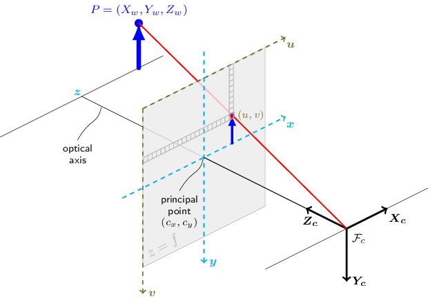
Prospective Projection is just 3D world coords to 2D image coords. However, this mapping may not exactly match what we see, cuz reference system is different
-
Image reference coords are different
-
k, l are centimeter -> pixel ratios
Perspective Projection Basic Transform
-
Mathematically, to not consider the upside-down image, we place the image plane in Front of the camera (like the symmetry)
-
-
Homogenous coords is just in the form (x/w,y/w) -> (x,y,w)
- reason why we use homogeneous coords: because
(u,v) = (-d*x/z, -d*y/z),1/zis non-linear transformation.-
(x,y,w)in homogeneous coords is(x/w, y/w), then you can use homogeneous transformation, which uses matrix multiplication. - easily converted back to
(-d*x/z, -d*y/z)
-
- There are 5 Intrinsics: focal lengths: fl, fk; 2 offsets; 1 skewness
- Pcamera = KCPworld = MPworld
- reason why we use homogeneous coords: because
-
Intrinsics
Perspective Projection in Homogenous Transform
- Considering skewness: Angle between x,y axes of image plane. That's due to camera manufacturing error.
Skewness in homogenous System
- Considering skewness: Angle between x,y axes of image plane. That's due to camera manufacturing error.
-
Extrinsics: 6 - 3 from rotation, 3 from translation
Extrinsics: 6 params
-
opencv solvepnp. P3P is just a pure geometry problem. You know: 1. A,B,C's 3D coords (on the same plane), 2. A', B', C' 2D coords. Now you can get 四面体棱长.
You know AP, BP, CP thru intrinsics
Then use 余弦定理 to solve for thetas, then 棱长
- Transformations: extrinsics: world frame to camera frame; Intrinsics: camera frame to image plane
- Extrinsics i just a regular SE(3) matrix
- alpha, beta are scale factors.
-
========================================================================
========================================================================
-
calibrateCamera: no skew param in intrinsics. Good explanation. The goal of calibration is to know the 6 extrinsics and 5 intrinsics, and skew params 从零开始学习「张氏相机标定法」
-
Model: We don't want to invert the image, so we put the image in front of the cam
-
three frames: world frame, camera frame (at the shutter), and image frame.
-
world frame -> camera frame

-
camera_frame -> image_frame: intrinsics. So if we know world frame, we know its image coord. But we can't go the other way


-
-
-
Calibration Derivation Version .
-
Homography(单应) describes the relationship between the same scene on two planes. If we assume zw = 0, is the
world -> (u,v).
-
Homography has 8 free variables, because it's homogenous coordinates, we can have everything times k, and they're still valid! So we can put a constraint (e.g., h33 = 1, or |H| = 1) , and can be solved with at least 4 pairs.

- SVD (using a different notation)
Calibration set up and SVD
- SVD (using a different notation)
-
With H solved, we can get two eqns for solving for intrinsics, M. M is a symmetric matrix, so it has 6 variables, and requires 6/2=3 different views.

-
-
How does calibrateCamera really calculate M (intrinsics) and [r1 r2 t] (extrinsics), and k (distorsion)? Using LM Optimiztion
- It tries to minimize the total reprojection error

- It tries to minimize the total reprojection error
-
Calibration under distortion, undistorsion
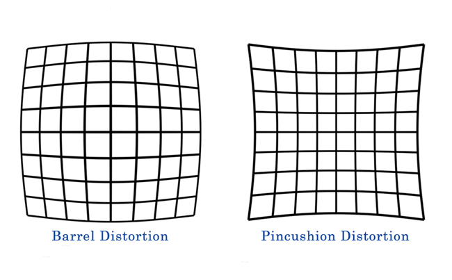
- Distortion
Distortion - requires non-linear optimization
- caused by light being bent more near the edges of a lens.
- barrel distortion is "center appears larger than edges"
- There's also tangential Distortion.
- Distortion
-
Fish-eye Camera Calibration
-
-
The image can be thought of as being stretched from normal, (x,y) -> (x'y')

-
x, y are the real camera coords we want to get.
-
Then
x_dist, y_distbecome the pixels we see:u=fx(x_dist+αy_dist)+cx v=fy*y_dist+cy -
So we want to get the
k1, k2, k3..., and OpenCV uses newton-raphson to optimize the reprojection error (against distorted image). Note in opencv, we just estimatek1, k2
-
-
cv2.fisheye.calibrateprovides better estimates of distorsion and intrinsics IF A CAMERA HAS A WIDE FOV (regular cameras' distortion won't qualify for that). But here are a few things to think about:- It's sensitive to the angles of images, so calibrating each camera individually is a good idea
-
cv2.calibrate()already considers barrel/pillow distortions. However, they don't work well on fish eye cams
-
new_cam_matrix = cv2.fisheye.estimateNewCameraMatrixForUndistortRectify(intrinsics, distortion, img_size): get a better intrinsics -
mapx2, mapy2 = cv2.fisheye.initUndistortRectifyMap(intrinsics, distortion, R (not sure), new_cam_matrix, img_size_after_undistortion): transform old img -> new image, map1 for x axis, map2 for y. -
Undistorted and rectified image:
# img_rectified = cv2.remap(img,    # 畸变的原始图像
#                           mapx2, mapy2,   # X 坐标和 Y 坐标的映射
#                           interpolation=cv2.INTER_LINEAR,     # 图像的插值方式
#                           borderMode=cv2.BORDER_CONSTANT)     # 边界的填充方式
- Note:
undistort()调用了initUndistortRectifyMap和remap, but the result is still different
- Note:
-

-
Stereo Camera Calibration
- opencv
stereoCalibrate(), output- R – Output rotation matrix between the 1st and the 2nd camera coordinate systems.
- T – Output translation vector between the coordinate systems of the cameras.
- E – Output essential matrix.
- F – Output fundamental matrix.
- opencv
-
Run time Disparity Image Generation
-
Image undistort
-
Stereo Rectification: Opencv uses these:

-
Right image frame -> left frame (This is
R, and we can identifyTas well)
-
rotate left frame -> perpendicular to T (this is R_rect)

-
Rotate the right camera by
R_rect
-
Rotate right camera by R, so we have two camera frames aligned like above
-
For each left camera point, calculate its position in the rectified image. Also do the same with the right camera

-
For the unpopulated pixels in the rectified image, find their position in the original image (otherwise there'd be holes)
-
-
Crop
-
For each point on the cropped image, do local window search for pixel matching, comparing left image against the right one

-
-
Verged Camera Model, Stereo views = multiple views, and we should find how they're related.

- Epipolar line is the intersection of plane (point and the two optical centers) and the two image planes
- When you have parallel camera views, the epipolar lines are parallel, too.
- Epipole is intersection of an image plane and the optical center line. All epipolar lines will go thru that
- For parallel camera views, epipoles are infinitely far.
- The epipolar lines will look verged (the camera view might be too small to show it though)
- with known intrinsics, one can know the epipole, then for each point, we can find the corresponding epipolar line on the other screen.
- Estimating shape from scene called "shape from X" used to be popular
- Simple Epipolar geometry for estimating depth
When two same cameras are parallel, if z is infinite, x2-x1 -> 0
- Epipolar line is the intersection of plane (point and the two optical centers) and the two image planes
-
Point Correspondence: On 2D, points are ambiguous
Points on the same ray from the ray to the optical center are the same point
-
Assume the same focal length, camera parallel, epipolar lines at the same y position
-
"soft" constraints on top of the "hard" epipolar constraints:
- Matching pixels should look about the same
- There should be at most one matching point
- Points A,B,C from left to right on the left image should be A,B,C from left to right on the right image.
- Disparity gradient is limited? Depth should remain the same.
-
So, the epipolar lines have the same height in this set up:
- Now we use Sum of Squared Difference to calculate the disparity, then find the best match
We take the SSD of a neighborhood, then find the best match
The lowest Point is the best match
- However, if two cameras have different scaling in intensity, you may get a different neighborhood with the lowest SSD. You can eliminate that using normalized correlation filter?
-
Normalized Correlation in Action:
Strong peak right there!
- But there're some "texture-less" patches, where you get good matches all over the place. what do we do? We gotta pick specific features, like the distinctive corners.
caption
-
Different scaling is also a problem.
-
Occulusion is a problem too.
You can see an image only partially.
- Ordering is a problem in this case, and modern stereo system doesn't handle it too well:
The fingers are swapped in two views
- This is called "window-based approach", and you need to tune the window size. Of course, we do this normalized-cross correlation matching pixel by pixel, individually.
Ground Truth: from RGBD camera
Does ok job
- More advanced techniques - we don't want to match points individually, we want to find that optimal set. Methods include: scanlines - dynamic programming, or even full 2d grid.
-
dynamic programming: We have a 2D correspondence graph for two lines. The overall correspondence can be thought of as a path, from right to left.
- Diagonal is the 1-1 correspondence, non 1-1 correspondence happens due to occlusion (some pixels visible to the left eye, but not to the right eye), so we're only considering 2 cases here.
The Juicy Part is How to assign Costs
- DP is already better, but there's a shift from line to line. That's because each line doesn't know the other lines.
DP is already better
-
Coherent Stereo on 2D grid: Kind of like Normalized Correlation + penalty on non-smoothness
- Disparity Image is the difference between the two images.
- non-smoothness is measured in a big-neighborhood than a window of interest. We assume that the disparity change within this neighborhood shouldn't be big
-
-
-
Essential Matrix and Fundamental Matrix
- Pixel Frame, relating one frame to another. 3*3 matrix, Rank 2 (because we have an epipolar constraint, which means epipolar lines on each scene will be co-planar), and we use 5 pt algorithm for calibration

- Fundamental Matrix: in camera frame. 7 dog, 8 pt algo?

- Pixel Frame, relating one frame to another. 3*3 matrix, Rank 2 (because we have an epipolar constraint, which means epipolar lines on each scene will be co-planar), and we use 5 pt algorithm for calibration
-
In openCV, we have semi-global block-matching:
-
Principle: get speckles (patches), then try to match speckles from one to another. (SGBM principle)
-
params (SGBM, params) - minDisparity:最小视差,默认为0。此参数决定左图中的像素点在右图匹配搜索的起点。int 类型
- numberOfDisparities+ minDisparity
-
reprojectTo3D(depth image, Q):-
z = f * baseline / disp
-
-
In Q (perspective transformation matrix) Everything is in homogenous coordinates. Derivation

-
normalize the image before outputting:
cv2.normalize(disparity, self.normalized_disparity, alpha=255, beta=0, norm_type=cv2.NORM_MINMAX), dst can be anything. can pass None -
Speckles: connected area?
-
-
Articles:
- Sum of Absolute Differences, SAD, trying to match blocks, in a range, find the block in the right image that has the lowest diff in the left
-
BM Principle, Block Matching implementation, BM
滑窗以图片的像素为中心,从上到下、从左到右依次滑动
对每一个滑窗:
    对每一个像素都计算出不同视差 d d d对应的SAD
    上述计算完成后,计算出在一个滑窗范围内所有像素对应相同的 d d d时SAD的和
从中选择使SAD的和最小的视差 d d d
    对最优 d d d进行检验:检验该区域内纹理值是否大于阈值,否则无效;检验最优 d d d是否唯一,否则无效;通过检验则视为当前像素的视差。滑动窗口,重复3-5完成对所有像素的计算。
- Article
- Characters of Opencv:
Build look up, space for time
-
Try to calculate:
imgl(x,y) <=> imgr(x-d,y) -
Challenges of Stereo System
- Camera Calibrations are wrong, so epipolar lines are wrong
- Specular Reflection
Specular Reflection is the perfect reflection that doesn't diffuse here and there
- Cameras are placed too far, so image planes don't have much overlapping
- Textureless Surfaces
- Occulusions
-
Aruco Markers Reading Materials
- Charuco is better
- Detect Markers
- AdaptiveThreshold (OTSU)
- Shape Detection (perimeter, polygon...)
- use down-sampled images to detect segments, and if there's another segment close to the end of the segment, then it's a child
- DFS, depth first search. Depth ==4, you should get the same square
- Extract bits
- Using homography to project (u,v) -> image plane
- If a pixel > threshold, then it's 1. else 0.
- Find the bits in the dictionary
- the code must be robust to rotation
-
April Tags
- QR code
- smaller payload, better accuracy
- talk with Jack: onboarding box 3D modelling, with 5 cameras around
- Take picture, put the item in, take another picture. masking using different lights (red, green for different retroreflective lights, like green backdrop for filming, then do a subtraction bw the before and after image) to find the area
- Shape detection: get the top camera view of the item, detect the shape of the item (box, or sylinder)
- For the shape of the item, we want to know its size and location (x,y of the center, and size (height, radius))
- for 2 faces of the item (5 cams for 5 faces), we sample a grid from the masked image. (so each camera view will have different angles right? occlusions?).
pytorch.grid_sampling() - Take the difference between the two views.
- Optimize on the size and location params using gradient descent, using the difference as the cost function (where is the code for this?)
- fuse the images together, and the brightest part is the top
- find the brightest part, then do cv2.fitrectangle. see if you can get a small error
- for 2 faces of the item (5 cams for 5 faces), we sample a grid from the masked image. (so each camera view will have different angles right? occlusions?).
- project the item to each surface, then visualize in meshlab/open3d as mesh object
- Preparation
- Eye-in-hand
- Eye to hand is also Ax = xB solver!
-
Important note: Our notation, Transform(A->B) is "in A, where is B", which is ROS's parent frame vs child frame. In openCV, they refer Transform(A->B) to the transform we need to applyto the coordinates of a point in A, so we get the point's coordinates in B. That's ROS's source frame and target frame. So it's Transform(B->A) in our notation. Therefore, their X is our X-1.
- So we have below mapping:
gTb = T_gripper_base bTc = T_base_camera cTt = T_camera_board X = X^(-1)-
CALIB_HAND_EYE_DANIILIDISis recommended
- rvec in openCV is actually
rotation * theta, see here
-
Important note: Our notation, Transform(A->B) is "in A, where is B", which is ROS's parent frame vs child frame. In openCV, they refer Transform(A->B) to the transform we need to applyto the coordinates of a point in A, so we get the point's coordinates in B. That's ROS's source frame and target frame. So it's Transform(B->A) in our notation. Therefore, their X is our X-1.


