Board chipKIT Max32 - RetroBSD/retrobsd GitHub Wiki
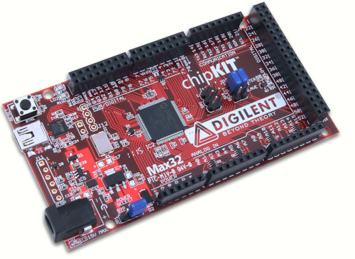
Max32 board (schematics, manual, Eagle files) is an Arduino compatible board, based on Microchip PIC32MX795 microcontroller.
Features:
- Microchip PIC32MX795 microcontroller 80 MHz (MIPS architecture)
- 83 usable i/o pins
- Compatible with Arduino Mega shields
- MiniUSB connector with FTDI convertor to UART1
- Power select switch: from USB or from external source
- External power connector
- One power LED and one user LED
- Reset button
Memory:
- 512 kbytes of Flash memory
- 12 kbytes of additional boot Flash memory
- 128 kbytes of RAM
Digital outputs can sink or source up to 18 mA. A rich set of peripheral functions is available: UART, SPI, I2C, ADC, timers. Two internal oscillators available: 8 MHz and 32 kHz. Power can be sourced from miniUSB, or from external power supply +7 ... 15 VDC.
Signals
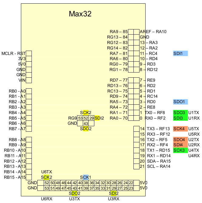
PWM/Digital connector
| Function | PIC32 | Signal | Signal | PIC32 | Function |
|---|---|---|---|---|---|
| VREF- | RA9 (28) | 85 | AREF | RA10 (29) | VREF+ |
      |RG13 (97)|  84  | GND  |  --     | GND
      |RG12 (96)|  83  | 13   |RA3  (59)| SDA2, LED
      |RG14 (95)|  82  | 12   |RA2  (58)| SCL2
      |RA7  (92)|  81  | 11   |RC4  (9) | SDI1
      |RA6  (91)|  80  | 10   |RD4  (81)|
      |RG0  (90)|  79  | 9    |RD3  (78)|
      |RG1  (89)|  78  | 8    |RD12 (79)|
      |RD7  (84)|  77  | 7    |RE9  (19)| INT2
      |RD13 (80)|  76  | 6    |RD2  (77)|
SOSCI |RC13 (73)| 75 | 5 |RD1 (76)| |RD9 (69)| 74 | 4 |RC14 (74)| SOSCO/ TDO |RA5 (61)| 73 | 3 |RD0 (72)| SDO1, INT0 TDI |RA4 (60)| 72 | 2 |RE8 (18)| INT1 TCK |RA1 (38)| 71 | 1 |RF8 (53)| SCL1A, SDO1A, U1ATX TMS |RA0 (17)| 70 | 0 |RF2 (52)| SDA1A, SDI1A, U1ARX
Communication connector
| Signal | PIC32 | Function |
|---|---|---|
| TX3 14 | RF13 (39) | SCK3A |
| RX3 15 | RF12 (40) | |
| TX2 16 | RF5 (50) | SCL3A, SDO3A |
| RX2 17 | RF4 (49) | SDA3A, SDI3A |
| TX1 18 | RD15 (48) | SCK1A |
| RX1 19 | RD14 (47) | |
| SDA 20 | RA15 (67) | SDA1, INT4 |
| SCL 21 | RA14 (66) | SCL1, INT3 |
Digital connector
| Function | PIC32 | Signal | Signal | PIC32 | Function |
|---|
                 |RC2  (7) | 22    | 23    |RC3  (8)  |
                 |VBUS (54)| 24    | 25    |RF3  (51) |
                 |RG3  (56)| 26    | 27    |RG2  (57) |
                 |RG15 (1) | 28    | 29 {3}|RG7  (11) | SDA2, SDI2A, U2ARX
                 |RE7  (5) | 30    | 31    |RE6  (4)  |
                 |RE5  (3) | 32    | 33    |RE4 (100) |
                 |RE3  (99)| 34    | 35    |RE2  (98) |
                 |RE1  (94)| 36    | 37    |RE0  (93) |
SCK1 |RD10 (70)| 38 | 39 |RD5 (82) | |RB11 (35)| 40 {a}| 41 {b}|RB13 (42) | |RB12 (41)| 42 {c}| 43 {4}|RG8 (12) | SCL2A, SDO2A, U2ATX VREF+ |RA10 (29)| 44 | 45 |RF0 (87) | |RF1 (88)| 46 | 47 |RD6 (83) | |RD8 (68)| 48 | 49 |RD11 (71) | SCL2A, SDO2A, U2ATX |RG8 (12)| 50 {1}| 51 {5}|RG7 (11) | SDA2, SDI2A, U2ARX SCK2A, U2BTX |RG6 (10)| 52 {2}| 53 {6}|RG9 (14) | U2BRX
Notes:
- {1} Also JP3, JP4
- {2} Also J13-03
- {3} Also JP3, JP4
- {4} Also JP3, JP4
- {5} Also JP3, JP4
- {6} Also J13-05
- {a} Also A11
- {b} Also A13
- {c} Also A12
Analog connector
| Signal | PIC32 | Function |
|---|---|---|
| A0 | RB0 (25) | PGED1 |
| A1 | RB1 (24) | PGEC1 |
| A2 | RB2 (23) | |
| A3 | RB3 (22) | |
| A4 | RB4 (21) | |
| A5 | RB5 (20) | |
| A6 | RB6 (26) | PGEC2 |
| A7 | RB7 (27) | PGED2 |
| A8 | RB8 (32) | |
| A9 | RB9 (33) | |
| A10 | RB10 (34) | |
| A11 {7} | RB11 (35) | |
| A12 {8} | RB12 (41) | |
| A13 {9} | RB13 (42) | |
| A14 | RB14 (43) | |
| A15 | RB15 (44) |
Notes:
- {7} Also 40
- {8} Also 42
- {9} Also 41
Power connector
| Signal | PIC32 | Function |
|---|---|---|
| RST | (13) | MCLR |
| 3V3 | VCC +3.3 | |
| 5V0 | VCC +5.0 | |
| GND | GND | |
| GND | GND | |
| VIN | External supply voltage |
UART and SPI pins
| UART | SPI | PIC32 | Connector |
|---|---|---|---|
| U1RX (U1ARX) | SDI3 | RF2 (52) | 0 - PWM/Digital, USB |
| U1TX (U1ATX) | SDO3 | RF8 (53) | 1 - PWM/Digital, USB |
| U3RX (U2ARX) | SDI2 | RG7 (11) | 29 - Digital, JP3-JP4 |
| U3TX (U2ATX) | SDO2 | RG8 (12) | 43 - Digital, JP3-JP4 |
| U2RX (U3ARX) | SDI4 | RF4 (49) | RX2 17 - Communication |
| U2TX (U3ATX) | SDO4 | RF5 (50) | TX2 16 - Communication |
| U4RX (U1BRX) | -- | RD14 (47) | RX1 19 - Communication |
| U4TX (U1BTX) | SCK3 | RD15 (48) | TX1 18 - Communication |
| U6RX (U2BRX) | -- | RG9 (14) | 53 - Digital, J13-05 |
| U6TX (U2BTX) | SCK2 | RG6 (10) | 52 - Digital, J13-03 |
| U5RX (U3BRX) | -- | RF12 (40) | RX3 15 - Communication |
| U5TX (U3BTX) | SCK4 | RF13 (39) | TX3 14 - Communication |
| -- | SCK1 | RD10 (70) | 38 - Digital |
| -- | SDI1 | RC4 (9) | 11 - PWM/Digital |
| -- | SDO1 | RD0 (72) | 3 - PWM/Digital |
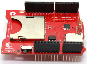
SD card shield
For SD and micro-SD cards, a MakerStudio SD Card Shield is recommended (User Guide, schematic). You can use only one card (either SD or micro-SD) on MakerStudio shield, alternatively selected by SW1 switch.
List of connections:
| Max32 | Signal | SD/MMC board |
|---|---|---|
| 4 | RC14 - /CS0 | CS card0 |
| 43 | RG8 - SDO2 | DI |
| 52 | RG6 - SCK2 | CLK |
| 51 | RG7 - SDI2 | DO |
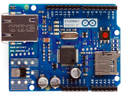
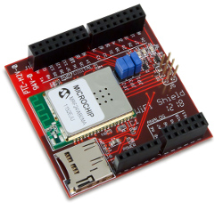
Ethernet and WiFi shields
Arduino Ethernet shield R3 or chipKIT WiFi shield would work as well: they have essentially the same connection schematics for micro-SD card.