Board Olimex PIC32 RetroBSD - RetroBSD/retrobsd GitHub Wiki
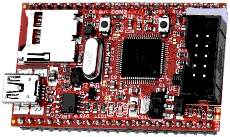
PIC32-RetroBSD is a tiny open hardware board (schematics, Eagle files) based on Microchip PIC32MX795 microcontroller, and targeted for RetroBSD developers.
PIC32-RetroBSD is essentially a variant of Pinguino-Micro development board, with MX440 microcontroller replaced with MX795 chip. It has more RAM and Flash memory, but most other features are the same, so the Pinguino-Micro User's Manual is still relevant.
Features:
- Microchip PIC32MX795 microcontroller 80 MHz (MIPS architecture)
- 40 i/o pins
- USB OTG controller with mini-USB connector
- SD card connector at SPI2
- On-board crystal 8 MHz
- Two user LEDs
- User button
- Reset button
- UEXT port for external UART/SPI/I2C peripherals
- miniICSP connector for PICkit programmer/debugger
Memory:
- 512 kbytes of Flash memory
- 12 kbytes of additional boot Flash memory
- 128 kbytes of RAM
Digital outputs can sink or source up to 18 mA. A rich set of peripheral functions is available: UART, SPI, I2C, ADC, timers.
Bootloader
To enter bootloader mode, press the BUT key first, hold it, then press and release the RST key. The LED will now flash and your board is ready to accept new code. The bootloader will appear as a HID device on your computer. Use pic32prog utility to program the Flash memory.
Early versions of PIC32-RetroBSD board were preprogrammed with outdated version of the bootloader, that did not properly react on BUT key. In this case, you can still enter bootloader mode if you short pin 14 (RD8) and pin 20 (GND) of CON1 and then press and release the RST key.
Signals
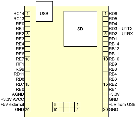
Connector CON1
| Signal | PIC32 | Function |
|---|---|---|
| 1 | RC14 (48) | SOSCO |
| 2 | RC13 (47) | SOSCI |
| 3 | RE0 (60) | |
| 4 | RE1 (61) | |
| 5 | RE2 (62) | |
| 6 | RE3 (63) | |
| 7 | RE4 (64) | |
| 8 | RE5 (1) | |
| 9 | RE6 (2) | |
| 10 | RE7 (3) | |
| 11 | RF1 (59) | |
| 12 | RG9 (8) | |
| 13 | RD11 (45) | INT4 |
| 14 | RD8 (42) | INT1, RTCC |
| 15 | RD7 (55) | |
| 16 | RB0 (16) | VREF+, PGED1 |
| 17 | -- | AGND |
| 18 | -- | +3.3V AVCC, see J1 |
| 19 | -- | +5V external |
| 20 | -- | GND |
Connector CON2
| Signal | PIC32 | Function |
|---|---|---|
| 1 | RD6 (54) | |
| 2 | RD5 (53) | |
| 3 | RD4 (52) | |
| 4 | RD3 (51) | U1TX |
| 5 | RD2 (50) | U1RX |
| 6 | RD1 (49) | LED2 (yellow) |
| 7 | RB14 (29) | |
| 8 | RB12 (27) | TDI |
| 9 | RB11 (24) | TDO |
| 10 | RB10 (23) | TMS |
| 11 | RB9 (22) | |
| 12 | RB8 (21) | |
| 13 | RB4 (12) | |
| 14 | RB3 (13) | |
| 15 | RB2 (14) | |
| 16 | RB1 (15) | PGEC1 |
| 17 | -- | +3.3V |
| 18 | -- | GND |
| 19 | -- | +5V from USB |
| 20 | -- | GND |
UEXT connector
| UEXT | PIC32 | Function |
|---|---|---|
| 1 | -- | +3.3v |
| 2 | -- | GND |
| 3 | RF5 (32) | U2TX, SCL2 |
| 4 | RF4 (31) | U2RX, SDA2 |
| 5 | RD10 (44) | SCL1, INT3 |
| 6 | RD9 (43) | SDA1, INT2 |
| 7 | RG7 (5) | SDI2, SD card |
| 8 | RG8 (6) | SDO2, SD card |
| 9 | RG6 (4) | SCK2, SD card, LED1 (green) |
| 10 | RF0 (58) | UEXT_#CS |
LEDs and button
| Signal | PIC32 | Function |
|---|---|---|
| LED1 | RG6 (4) | Green, UEXT/9, SD card |
| LED2 | RD1 (49) | Yellow, CON2/6 |
| Button | RD0 (46) | Active low, see BUT_J |
UART pins
| UART | PIC32 | Connector |
|---|---|---|
| U1RX | RD2 (50) | CON2/5 |
| U1TX | RD3 (51) | CON2/4 |
| U2RX | RF4 (31) | UEXT/4 |
| U2TX | RF5 (32) | UEXT/3 |
SPI pins
| SPI | PIC32 | Connector |
|---|---|---|
| SCK2 | RG6 (4) | UEXT/9, SD card, LED1 (green) |
| SDI2 | RG7 (5) | UEXT/7, SD card |
| SDO2 | RG8 (6) | UEXT/8, SD card |