UML - RJAE5/2143-OOP GitHub Wiki
Universal Modeling Language (UML)
The industry standardized visual language used for modeling and designing software systems is known as UML. It provides a set of diagram types to represent different aspects of a system, including its structure, behavior, and interactions. UML helps developers, analysts, and more communicate system designs clearly and effectively throughout the development lifecycle.
Structural Diagrams
Structural diagrams mainly focus on how a system is at any one point during the runtime of a program, representing its components and how they interact with one another.
- Class Diagram
- Represents the system's classes, attributes, methods, and other relationships.
- Object Diagram
- Shows instances of objects and their relationships at a particular point in time.
- Component Diagram
- Illustrates the physical components of a system and their interactions.
- Deployment Diagram
- Displays the hardware architecture and how software components are deployed on it.
- Package Diagram
- Organizes the system into packages to show dependencies between groups of classes.
Class Diagram Example
The following image illustrates a Team class which is related to a Player class.
Behavioral Diagram
Behavioral diagrams often describe the dynamic interactions of a system, including processes, and state changes over time.
- Use Case Diagram
- Depicts the functional requirements of the system from an end-user perspective.
- Sequence Diagram
- Shows the sequence of messages exchanged between objects to carry out a particular functionality.
- Activity Diagram
- Models the flow of control and data within a system or process, often used for workflows.
- State Diagram
- Represents the states of an object and the transitions between them in response to events.
- Communication Diagram
- Similar to sequence diagrams but focuses on the objects involved and their interactions.
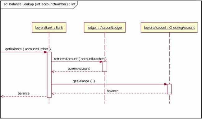
Sequence Diagram Example
The following image depicts a sequence diagram of the process of retrieving a balance within a certain bank account given an inheritance chain.
Interaction Diagrams
Interaction diagrams emphasize the communication and interaction between components or objects.
- Interaction Overview Diagram
- Combines activity and sequence diagrams to show the flow of control and interactions.
- Timing Diagram
- Focuses on the timing constraints of the interactions between components over a period of time.
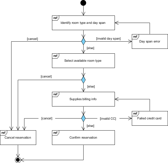
Interaction Overview Diagram Example
The following interaction overview diagram shows the process of reserving a hotel room and all potential outcomes/loops.
Implementation Diagrams
Implementation diagrams focus on the details of how system components will be implemented and deployed
- Component Diagram
- Shows the organization of software components and their dependencies.
- Deployment Diagram
- Represents the system's physical deployment on hardware and the relationships between the components.
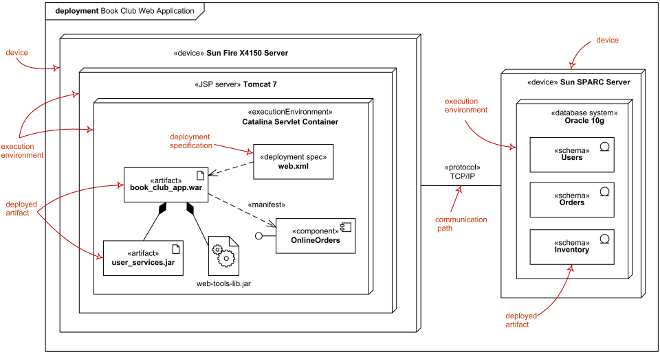
Deployment Diagram Example
The following deployment diagram represents the overall deployment of a Book Club Web App.
Important Notes
- UML provides a standardized way of communicating expectations and outcomes for software.
- There is a large variety of UML diagrams for almost every particular need.
- In OOP, UML can help visualize the complex interactions that occur between objects.
Sources:
- https://cdn-proxy.slickplan.com/wp-content/uploads/2023/10/5_uml.png
- https://developer.ibm.com/developer/default/articles/the-sequence-diagram/images/3101_figure2.jpg
- https://cdn-images.visual-paradigm.com/guide/uml/what-is-interaction-overview-diagram/08-interaction-overview-diagram-example-room-reservation.png
- https://www.uml-diagrams.org/deployment-diagrams/deployment-diagram-overview-specification.png
- https://en.wikipedia.org/wiki/Unified_Modeling_Language
- https://www.geeksforgeeks.org/unified-modeling-language-uml-introduction/