RFE_IoT_GetPeak example - RFExplorer/RFExplorer-IoT-for-Arduino GitHub Wiki
This is a very simple, “Hello World” equivalent example to understand how RF Explorer 3G+ IoT library works.
What it does
Initializes the RF module, then request configuration details and check for peak signal value in Amplitude and Frequency within the default RF scanning range.
How to run it
Upload the RFE_IoT_GetPeak example into the Arduino Due and see the results in the Arduino Serial Monitor.
Optional: A signal source such as RF Explorer Signal Generator, tuned at 1.2GHz will be useful to show actual signal activity.
Expected results
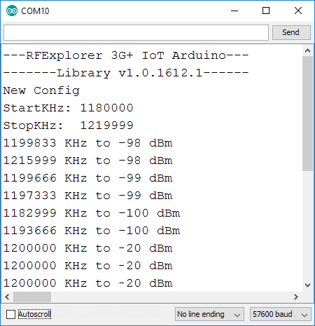
As depicted below, the output on the Serial Monitor includes the following information:
- IoT Library header and version
- A print report indicating New Config while the module is reporting current configuration
- A couple of print details with start/stop frequency scan range as defined by the current default settings in the RF module. For the sake of simplicity, this example does not change default settings set as 1.180 – 1.220GHz.
- Continuous scan of this range, with report of peak signal value detected in such range.
- In the report below, we can see normal scan is noise floor for a while (no real RF activity detected). Levels in the range of -98 to -100dBm are noise floor, no real signal detected.
- At some point a clear, powerful 1.2GHz signal is start to transmit nearby and therefore detected, as -20dBm signal.
Detailed source code description
As described in the library reference, the setup() function configures the required communication, with some intermediate delays to guarantee correct hardware initialization.
After that, the Arduino sketch will run loop() function continuously capturing all scans from the RF Explorer 3G+ IoT module.