4.Concept Generation - R-division-2020-2021-even/Repo-01 GitHub Wiki
| SI NO | Functions from User Perspective | Functions from Designer Perspective |
|---|---|---|
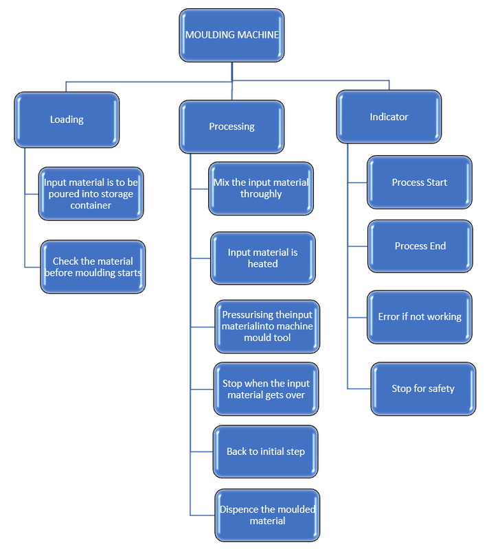
| 1 | Machine should mould different structures | Check the material before moulding starts |
| 2 | Choose a proper mould box | |
| 3 | Notify when the process begins | |
| 4 | Should have a timer installed | |
| 5 | Start the timer | |
| 6 | Check the shape obtained | |
| 7 | Notify the completion of process | |
| 8 | Dispence the moulded material | |
| 9 | Stop when overloded | |
| 10 | Dispose the waste | |
| 11 | Indictate power supply | |
| 12 | Stop when overloded | |
| 13 | Should alert when input material gets over |
| SI NO | Subunctions | Mean 1 | Mean 2 | Mean 3 | Mean 4 |
|---|---|---|---|---|---|
| 1 | Sensing |
 Infrared sensor Infrared sensor |
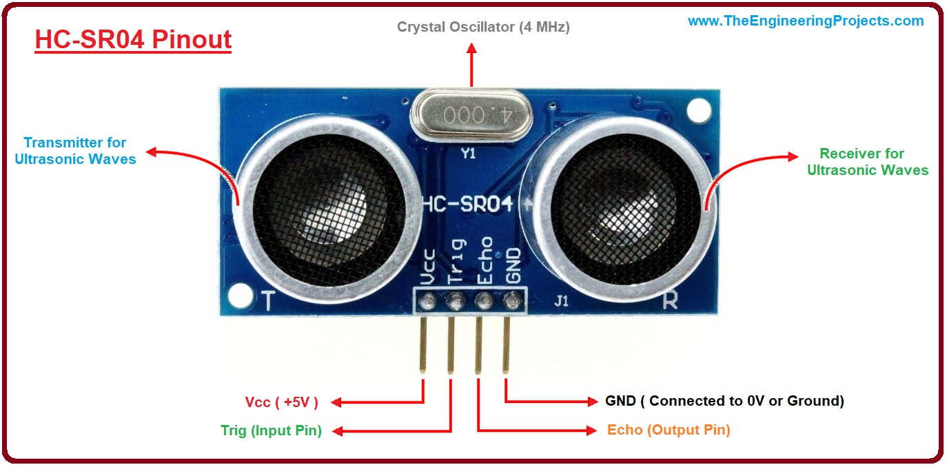 Ultrasonic sensor Ultrasonic sensor |
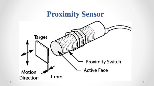 Proximity sensor Proximity sensor |
 Photoelectric Sensor Photoelectric Sensor |
| 2 | Mould moment |
 Conveyer Conveyer |
 Roller conveyer Roller conveyer |
 Pneumatic conveyer Pneumatic conveyer |
 Chute conveyer Chute conveyer |
| 3 | Indication system |
 Buzzer Buzzer |
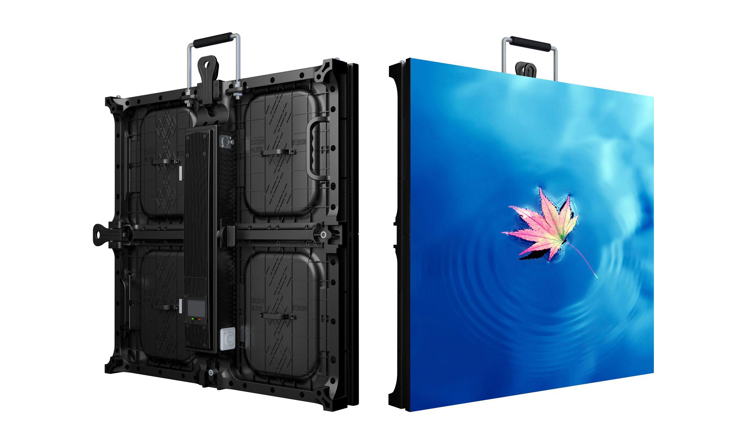 LED screen display LED screen display |
 LED lights LED lights |
 Speaker Speaker |
| 4 | Heating system |
 Induction heating system Induction heating system |
 Infrared heating system Infrared heating system |
 Convection air heating system Convection air heating system |
 Resistance power heating system Resistance power heating system |
| 5 | Cutting tool |
 Ball end Ball end |
 Toroidal Toroidal |
 Bull nose Bull nose |
 Square end Square end |
| 6 | Plungers used |
 Pin plunger Pin plunger |
 Ball plunger Ball plunger |
||
| 7 | Clamping units |
 Mechanical toggle clamp Mechanical toggle clamp |
 Hydraulic clamp Hydraulic clamp |
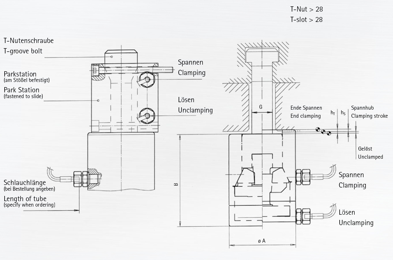 Hydro-mechanical clamp Hydro-mechanical clamp |
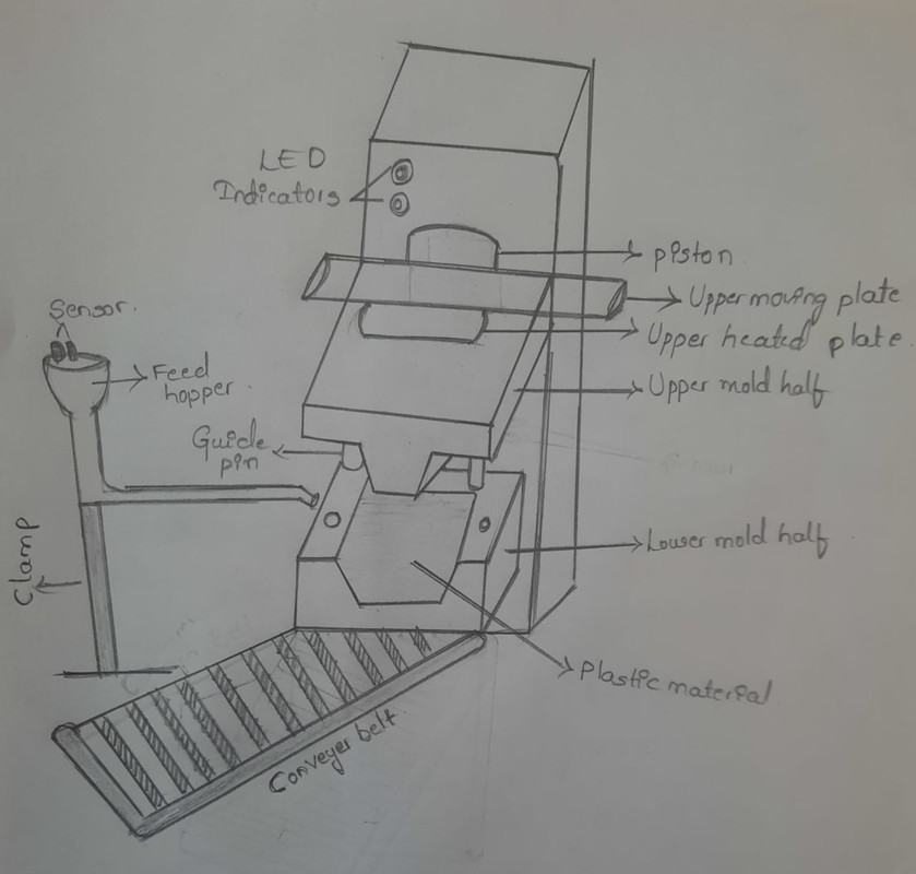
DESCRIPTION :In this Process, the input material will be kept in the mould of a required shape of the component and is subjected to the heating process.During heating, the liquid will undergo the following changes i.e. liquid will undergo in the form of a gel, and by the application of pressure, it turns to solid.After that, the Compression load is applied at the gel condition of the liquid so that the shaping of the component takes place.Heating converts the liquid into solid whereas, compression load will give the shape to the component. Process of compression takes place through hydraulic pressing.
Hydraulic press: Machine that makes use of static pressure of the liquid to process metals, plastic,rubber,wood,etc.
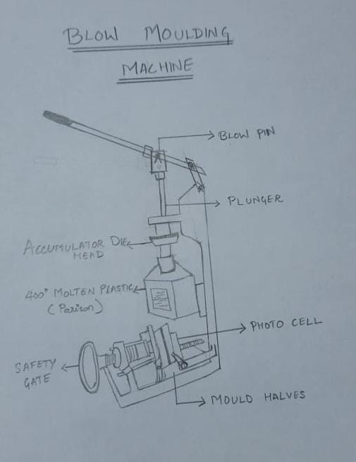
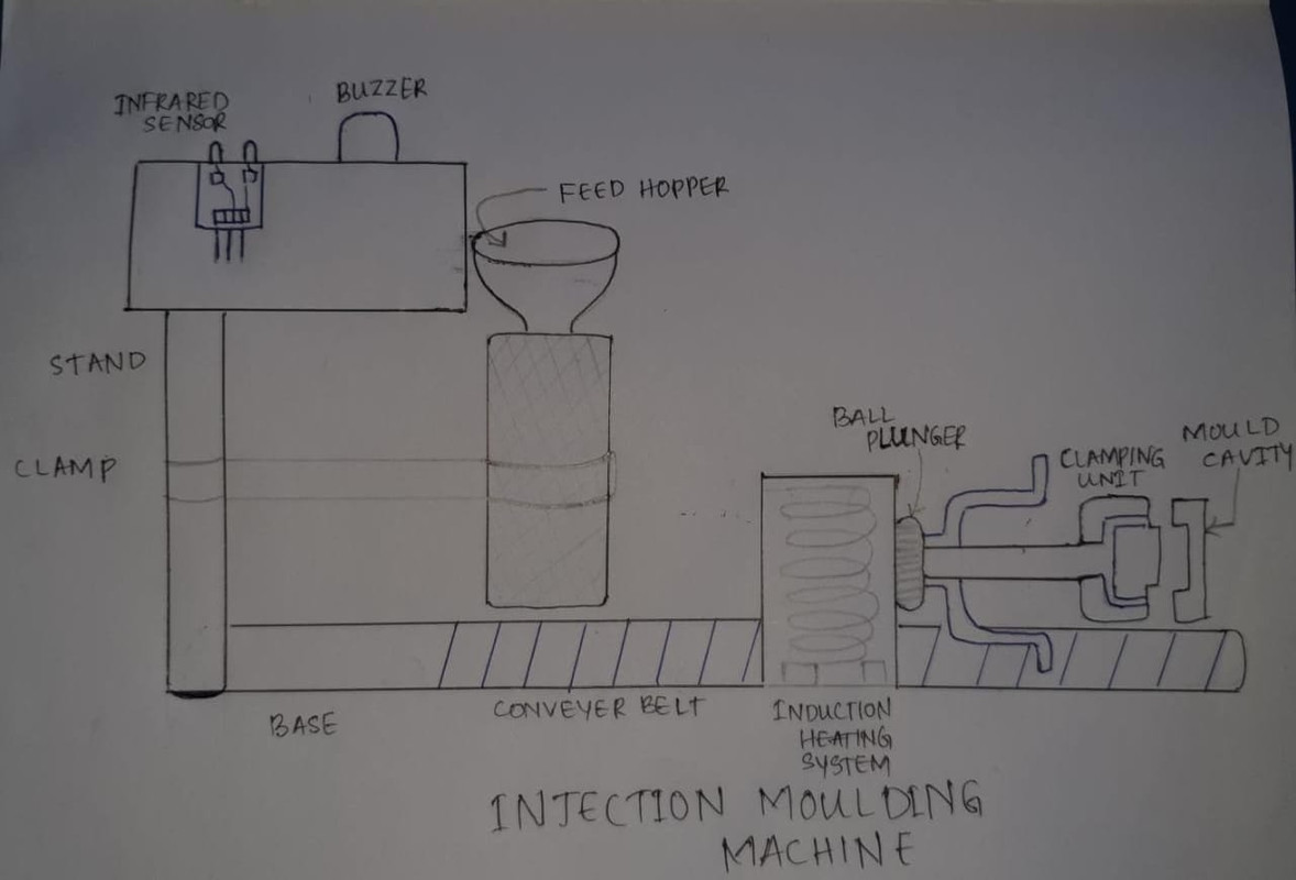
DESIGN DESCRIPTION : The screw assembly helps to melt the polymer. The molten polymer is fed into a hot runner where it is injected through nozzles into a heated cavity and core pin. The cavity mold forms the external shape and is clamped around a core rod which forms the internal shape of the preform. The preform consists of a fully formed bottle/jar neck with a thick tube of polymer attached, which will form the body. similar in appearance to a test tube with a threaded neck. The preform mold opens and the core rod is rotated and clamped into the hollow, chilled blow mold. The end of the core rod opens and allows compressed air into the preform, which inflates it to the finished article shape.
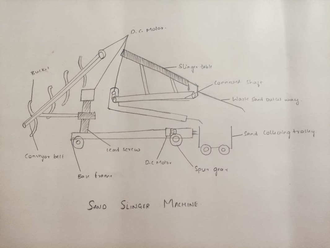
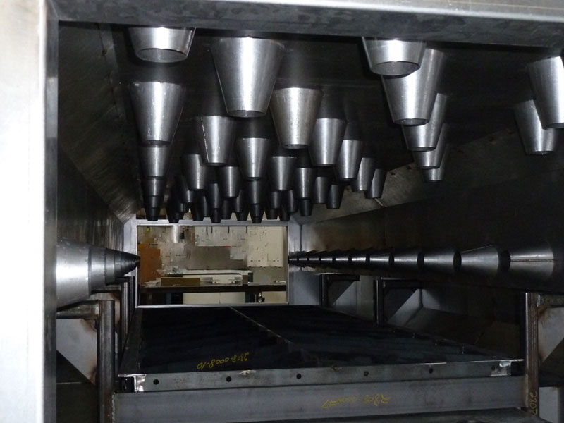
DESIGN DESCRIPTION : A sand slinger is an automatic machine equipped with a unit that throws sand rapidly and with great force into the mould box. Figure shows a sand slinger. Sand slinger consists of a base, sand bin, bucket elevator, belt conveyor, ramming head and a swinging arm.In operation, the pre-mixed sand mixture from the sand bin is picked by the bucket elevator and is dropped on to the belt conveyor. The conveyor carries the sand to the ramming head, inside which there is a rotating impeller having cup shaped blades rotating at high speeds.