GATHERING PERTINENT INFORMATION . - Q-Division-2019-2020-Even/Team-18 GitHub Wiki
GAMING MACHINE.
A gaming machine is defined by the Gambling Act 2005 as a machine that is designed or adapted for use by individuals to gamble (whether or not it can also be used for other purposes).
Gaming machines fall into categories depending on the maximum stake and prize available. Most gaming machines are of the reel-based type, also known as fruit, slot, or jackpot machines.
Several devices or systems are excluded from being defined as gaming machines including:
domestic or dual-use computers telephones or other machines for facilitating communication machines designed or adapted to bet on future real events lottery terminals in a bingo premises, machines designed or adapted for the playing of bingo (including by way of prize gaming) machines designed or adapted for the playing of bingo, by way of prize gaming, where a family entertainment centre gaming machine permit or a prize gaming permit is held semi-automated casino games wholly-automated casino games.
An electronic game is a game that employs electronics to create an interactive system with which a player can play. Video game is the most common form today, and for this reason the two terms are often mistakenly used synonymously. Other common forms of electronic game include such products as handheld electronic games, standalone systems (e.g. pinball, slot machines, or electro-mechanical arcade games), and exclusively non-visual products (e.g. audio games).
The earliest form of dedicated console, handheld electronic games are characterized by their size and portability. Used to play interactive games, handheld electronic games are often miniaturized versions of video games. The controls, display and speakers are all part of a single unit, and rather than a general-purpose screen made up of a grid of small pixels, they usually have custom displays designed to play one game. This simplicity means they can be made as small as a digital watch, which they sometimes are. The visual output of these games can range from a few small light bulbs or LED lights to calculator-like alphanumerical screens; later these were mostly displaced by liquid crystal and Vacuum fluorescent display screens with detailed images and in the case of VFD games, color. Handhelds were at their most popular from the late 1970s into the early 1990s. They are both the precursors to and inexpensive alternatives to the handheld game console.
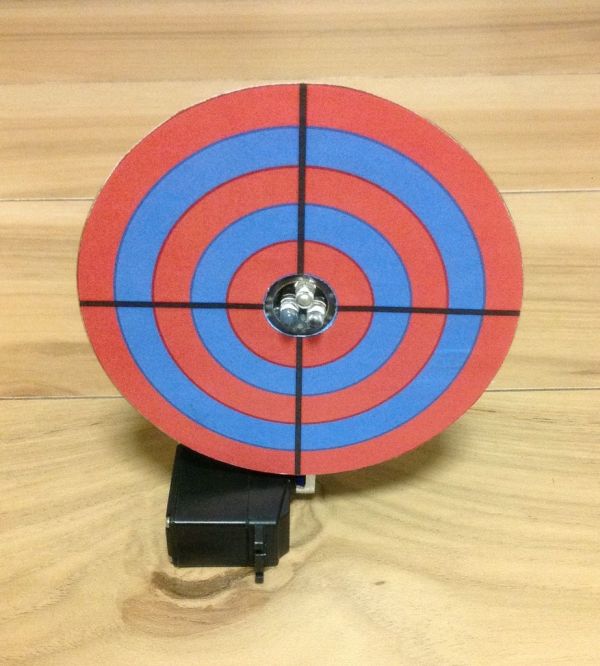
Game 1.Laser Shooting Game
This laser game is a simple project that utilizes an Arduino mini. All target boards have an Arduino, sensors, and servo control ports. Shooting the target center triggers the servo and the board falls flat.
Step 1:What you need Major Components in Project Bill of material:
- Shooting Target board PCB (attached gerber file)
- Servo
- Photo diode x 3
- IR transmitter x 1
- IR receiver x 1
- 9014 NPN transistors x 3\
- Pins and socket
- Arduino Mini x 2
- SMD components (Caps, resistors)
- CD
- Target board graphic (CD size)
- Toy laser gun
Step 2: Soldering
Step 3: Prepare the target board Cut out the and stick it on the CD by glue The diameter of the CD is 120 mm and the inner diameter is 15 mm.
Step 4: Glue the PCB on servo arm Use the hot glue gun to glue the assembled PCB on the servo arm. Please reserved some space between the servo and the PCB. As the servo chassis may collide with the PCB during servo arm moment.
Step 5: Stick the target board on the PCB
Game 2.
Arduino Shooting Game Arcade Electronics
LED Super Bright Red LED * 150 nos RGB LED * 12 (Common Cathode) IC & Transistors MAX 7219 ic * 2 2N2222 npn transistors * 6 Resistors 220 Ohm * 100 1M Ohm * 6 10K Ohm * 2 Capacitors 10uF (electrolytic) * 2 100nF (Disc) * 2 Other PCB large size * 3 IC Socket 24 pin * 2 2 pin female header * 6 Headers - As per requirement More connectors as per requirement. Hardware
Laser Pointer Toy Gun (Or simply laser gun) Glass Bowls * 6 Tools
Soldering iron metal & flux Hacksaw blade or any cutting tool Step 2: Here Is the Sensor !!! In my test, results were as follow for Red LED -
-
Dark / minimum light = 0.00 to 0.03 Volts
-
Bright light = 0.15 to 0.5 Volts
But the magic is here - when exposed to laser
- Laser Light = 1.5 Volts max & 0.5 to 1.2 Volt regular
(green and yellow led also works fine)
And main thing - Use super bright LEDs.
Step 3: Block Diagram. How It Works !!!
 Here is the overall block diagram of this project.
Sensor modules - Sensor modules are connected to arduino's analog pins. We have 6 analog i/p pins so I made 6 modules. And Because there are 6 modules so connected 6 modules to 6 digital output pins. Laser triggers the LED module and send signal to arduino. LEDs glow by arduino's digital o/p pins via transistor module. Let's see it in next step. That's all about sensor modules.
RGB circuit - Second part is of indication, decoration purpose that I used rgb led's. I think you may know about MAX 7219 ic, if not then it is used for led matrix, multiple 7 segment displays as driver & uses only 3 arduino pins. I used this ic because - 1) Limited no. of arduino o/p pins 2) Code & connections are simple 3) easy to use . This ic is the most costly component in whole project.
Matrix - Third and last part is display module (Matrix). I made one 8 X 8 led matrix (As we are already using much LED's then why to buy separate led matrix display.) So made one matrix of 64 LED's. It also uses one more max 7219 IC as driver. It takes signal from previous 7219 IC. So this saves arduino pins
Step 4: LED (Sensor) Input As Well As Output Step 4: LED (Sensor) Input As Well As Output Step 5: Let's Make Sensor Panels
Step 6: Preparing PCB Step 7: Check LED, Beware of Pins Step 8: Soldering LEDs (Cathode)
Step 9: Soldering LEDs (Anode) Step 10: Testing Modules Step 11: Final Touch to Sensor Panels Step 12: Let's Make Transistor Panel Shooting game arcade
Duck hunt gearing and movement testing. Slider crank mechanism. Rack and pinnion method.
Servo Motor : types and working principle explained.

The servo motor is most commonly used for high technology devices in the industrial applications like automation technology. It is a self contained electrical device, that rotates parts of machine with high efficiency and great precision. Moreover the output shaft of this motor can be moved to a particular angle. Servo motors are mainly used in home electronics, toys, cars, airplanes and many more devices.
Thus this blog discusses the definition, types, mechanism, principle, working, controlling, and lastly the applications of a servo machine.
Definition : A servo motor is a rotary actuator or a motor that allows for a precise control in terms of the angular position, acceleration, and velocity. Basically it has certain capabilities that a regular motor does not have. Consequently it makes use of a regular motor and pairs it with a sensor for position feedback .
Types of servo motors : Servo motors can be of different types on the basis of their applications. The most important amongst them are : AC servo motor, DC servo motor, brushless DC servo motor, positional rotation servo motor, continuous rotation servo motor, and linear servo motor.
A typical servo motor comprises of three wires namely- power, control, and ground. The shape and size of these motors depends on their applications.
- DC servo motor : The basic operating principle of DC motor is the same as other electromagnetic motors. The design, construction, and the modes of operation are different. The rotors of this kind of motor are designed with long rotor length and smaller diameters. Their size is larger than that of conventional motors of same power ratings.

There are various types of dc servo motors which are :
1. Series motors :
The series motors have a high starting torque and draws large current. The speed regulation of this kind of motor is poor.
2. Split series motor :
They are the motors with split-field rate with some fractional kilowatts. Split series motor has a typical torque-speed curve. This curve denotes high stall torque and a rapid reduction in torque with high speed.
3. Shunt control motor :
It has two separate windings:
1.field winding – on the stator.
2.armature winding – on the rotor of the machine.
Both windings are connected to a dc supply source.
4. Permanent magnet shunt motor :
It is a fix excitation motor where the field is actually supply by a permanent magnet. Furthermore, the performance is similar to armature controlled fixed field motor.
2. AC servo motor :
AC servomotors are AC motors in which incorporate encoders are use with controllers for providing feedback and close-loop control. Hence, these motors can be positioned to high accuracy. Thus they can be controlled exactly as per requirement for the application.
The classification of AC servomotors is done into two types. These are 2 phase and 3 phase AC servo motor. Now most of the AC servomotors are of the two-phase squirrel cage induction motor type. They are used for low power applications. Furthermore the three phase squirrel cage induction motor is now utilized for applications where high power system are in use.

- Brushless DC servomotor : BLDC motors are also commonly known as electronically commutated motors or synchronous motors powered by DC electricity via inverter or switching power supply. Hence this provides an AC electric current to drive each phase of motor via a closed loop controller. The controller provides pulses of current to the motor windings that control the speed and torque of the motor.
The construction of a brushless motor system is typically similar to a permanent magnet synchronous motor. Finally the advantages of the brushless motor over brushed motors are high power to weight ratio, high speed, and electronic control. The brushless motors find applications in such places as computer peripherals ( disk drives, printers ), hand-held power tools, and vehicles ranging from model aircrafts to automobiles.
4. Positional rotation servo motor :
Positional rotation servo motor is the most important servo motor. Hence it is also the most common type of servo motor. The shaft output rotates in about 180 degree. Additionally it includes physical stops located in gear mechanism to stop turning outside these limits to guard the rotation sensor. These common servos involve in radio controlled water, ratio controlled cars, aircraft, robots, toys and many other applications.
5. Continuous rotation servo motor :
Continuous rotation servo motor relates to the common positional rotation servo motor, but it can go in any direction indefinitely. The control signal, rather than setting the static position of the servo, is understood as speed and direction of rotation. The range of potential commands sources the servo to rotate clockwise or anticlockwise as preferred, at changing on the command signal. Thus this type of motor is used in a radar dish if you are riding, one on a robot or you can use one as a drive motor on a mobile robot.

6. Linear servo motor :
Linear servo motor is also similar to the positional rotation servo motor discussed above, but with extra gears to alter the output from circular to back and forth. Although these servo motors are not likely to be found, but sometimes you can find them at hobby stores where they are used as actuators in higher model airplanes .
 Principle of working :
Servo motor works on the PWM ( Pulse Width Modulation ) principle, which means its angle of rotation is controlled by the duration of pulse applied to its control PIN. Basically servo motor is made up of DC motor which is controlled by a variable resistor (potentiometer) and some gears.
Principle of working :
Servo motor works on the PWM ( Pulse Width Modulation ) principle, which means its angle of rotation is controlled by the duration of pulse applied to its control PIN. Basically servo motor is made up of DC motor which is controlled by a variable resistor (potentiometer) and some gears.
Mechanism of servomotor : Basically a servo motor is a closed-loop servomechanism that uses position feedback to control its motion and final position. Moreover the input to its control is a signal ( either analogue or digital ) representing the position commanded for the output shaft .
The motor is incorporates some type of encoder to provide position and speed feedback. In the simplest case, we measure only the position. Then the measured position of the output is compared with the command position, the external input to controller. Now If the output position differs from that of the expected output, an error signal generates. Which then causes the motor to rotate in either direction, as per need to bring the output shaft to the appropriate position. As the position approaches, the error signal reduces to zero. Finally the motor stops.
The very simple servomotors can position only sensing via a potentiometer and bang-bang control of their motor. Further the motor always rotates at full speed. Though this type of servomotor doesn’t have many uses in industrial motion control, however it forms the basis of simple and cheap servo used for radio control models.
Servomotors also find uses in optical rotary encoders to measure the speed of output shaft and a variable-speed drive to control the motor speed. Now this, when combined with a PID control algorithm further allows the servomotor to be in its command position more quickly and more precisely with less overshooting .
Working of servomotors : Servo motors control position and speed very precisely. Now a potentiometer can sense the mechanical position of the shaft. Hence it couples with the motor shaft through gears. The current position of the shaft is converted into electrical signal by potentiometer, and is compared with the command input signal. In modern servo motors, electronic encoders or sensors sense the position of the shaft .
We give command input according to the position of shaft . If the feedback signal differs from the given input, an error signal alerts the user. We amplify this error signal and apply as the input to the motor, hence the motor rotates. And when the shaft reaches to the require position , error signal become zero , and hence the motor stays standstill holding the position.
The command input is in form of electrical pulses . As the actual input to the motor is the difference between feedback signal ( current position ) and required signal, hence speed of the motor is proportional to the difference between the current position and required position . The amount of power require by the motor is proportional to the distance it needs to travel .
Controlling of servomotors : Usually a servomotor turns 90 degree in either direction hence maximum movement can be 180 degree . However a normal servo motor cannot rotate any further to a build in mechanical stop.
We take three wires are out of a servo : positive , ground and control wire. A servo motor is control by sending a pulse width modulated(PWM) signal through the control wire . A pulse is sent every 20 milliseconds. Width of the pulses determine the position of the shaft .
for example ,
A pulse of 1ms will move the shaft anticlockwise at -90 degree , a pulse of 1.5ms will move the shaft at the neutral position that is 0 degree and a pulse of 2ms will move shaft clockwise at +90 degree.
 When we command a servo motor to move by applying pulse of appropriate width, the shaft moves to and holds the require position of the shaft. However the motor resists to change . Pulses need repetition for the motor to hold the position .
Applications :
-
Robotics : At every joint of the robot, we connect a servomotor. Thus giving the robot arm its precise angle.
-
Conveyor belts : servo motors move , stop , and start conveyor belts carrying product along to various stages , for example , in product packaging/ bottling, and labelling .
-
Camera auto focus : A highly precise servo motor build into the camera corrects a camera lens to sharpen out of focus images.
-
Solar tracking system : Servo motors adjust the angle of solar panels throughout the day and hence each panel continues to face the sun which results in harnessing maximum energy from sunup to sundown .
Mechanisms.
1.Rack and pinion
A rack and pinion is a type of linear actuator that comprises a circular gear (the pinion) engaging a linear gear (the rack), which operate to translate rotational motion into linear motion. Driving the pinion into rotation causes the rack to be driven linearly. Driving the rack linearly will cause the pinion to be driven into a rotation.
For example, in a rack railway, the rotation of a pinion mounted on a locomotive or a railroad car engages a rack placed between the rails and helps to move the train up a steep gradient.
For every pair of conjugate involute profile, there is a basic rack. This basic rack is the profile of the conjugate gear of infinite pitch radius (i.e. a toothed straight edge).[1]
A generating rack is a rack outline used to indicate tooth details and dimensions for the design of a generating tool, such as a hob or a gear shaper cutter.[1]
Rack and pinion combinations are often used as part of a simple linear actuator, where the rotation of a shaft powered by hand or by a motor is converted to linear motion.
The rack carries the full load of the actuator directly and so the driving pinion is usually small, so that the gear ratio reduces the torque required. This force, thus torque, may still be substantial and so it is common for there to be a reduction gear immediately before this by either a gear or worm gear reduction. Rack gears have a higher ratio, thus require a greater driving torque, than screw actuators.

1.1 Steering
A rack and pinion is commonly found in the steering mechanism of cars or other wheeled, steered vehicles. Rack and pinion provides less mechanical advantage than other mechanisms such as recirculating ball, but less backlash and greater feedback, or steering "feel". The mechanism may be power-assisted, usually by hydraulic or electrical means.
The use of a variable rack (still using a normal pinion) was invented by Arthur Ernest Bishop[2] in the 1970s, so as to improve vehicle response and steering "feel," especially at high speeds. He also created a low cost press forging process to manufacture the racks, eliminating the need to machine the gear teeth.

1.2 Rack railways
Rack railways are mountain railways that use a rack built into the center of the track and a pinion on their locomotives. This allows them to work on steep gradients, up to 45 degrees, as opposed to conventional railways which rely on friction alone for locomotion. Additionally, the rack and pinion addition provides these trains with controlled brakes, and reduces the effects of snow or ice on the rails.

1..3 Actuators
A rack and pinion with two racks and one pinion is used in actuators. An example is pneumatic rack and pinion actuators that can be used to control valves in pipeline transport. The actuators in the picture on the right are used to control the valves of large water pipeline. In the top actuator, a gray control signal line can be seen connecting to a solenoid valve (the small black box attached to the back of the top actuator), which is used as the pilot for the actuator. The solenoid valve controls the air pressure coming from the input air line (the small green tube). The output air from the solenoid valve is fed to the chamber in the middle of the actuator, increasing the pressure. The pressure in the actuator's chamber pushes the pistons away. While the pistons are moving apart from each other, the attached racks are also moved along the pistons in the opposite directions of the two racks. The two racks are meshed to a pinion at the direct opposite teeth of the pinion. When the two racks move, the pinion is turned, causing the attached main valve of the water pipe to turn.[3][4]

2.Slider crank
A slider-crank linkage is a four-link mechanism with three revolute joints and one prismatic, or sliding, joint.[1] The rotation of the crank drives the linear movement the slider, or the expansion of gases against a sliding piston in a cylinder can drive the rotation of the crank.
There are two types of slider-cranks: in-line and offset.
2.1 In-line:
An in-line slider-crank has its slider positioned so the line of travel of the hinged joint of the slider passes through the base joint of the crank. This creates a symmetric slider movement back and forth as the crank rotates.
2.2 Offset:
If the line of travel of the hinged joint of the slider does not pass through the base pivot of the crank, the slider movement is not symmetric. It moves faster in one direction than the other. This is called a quick-return mechanism.

Information collected by various sources.
| SI.NO | Components or parts used | Mechanism or working principle identified | Links |
|---|---|---|---|
| 1. | Servo motor | A servo motor is a rotary actuator or a motor that allows for a precise control in terms of the angular position, acceleration, and velocity. | https://engineering.eckovation.com/servo-motor-types-working-principle-explained/ |
|
|||
| 2. | DC motor | The DC motor is the device which converts the direct current into the mechanical work. It works on the principle of Lorentz Law, which states that “the current carrying conductor placed in a magnetic and electric field experience a force”. And that force is called the Lorentz force | https://en.m.wikipedia.org/wiki/DC_motor |
| 3. | Rack amd pinion | Rack and pinion gears are used to convert rotation into linear motion. A perfect example of this is the steering system on many cars. The steering wheel rotates a gear which engages the rack. As the gear turns, it slides the rack either to the right or left, depending on which way you turn the wheel. | https://en.m.wikipedia.org/wiki/Rack_and_pinion |
| 4. | Slider crank | A slider-crank linkage is a four-link mechanism with three revolute joints and one prismatic, or sliding, joint. The rotation of the crank drives the linear movement the slider, or the expansion of gases against a sliding piston in a cylinder can drive the rotation of the crank. | https://en.m.wikipedia.org/wiki/Slider-crank_linkage |
REFERENCES
- https://www.amazon.com/Bundaloo-Duck-Shooting-Game-Carnival/dp/B07V1WQ7DK
- https://www.elprocus.com/laser-sensor-working-and-its-applications/
- https://www.instructables.com/id/Arduino-Shooting-Game-Arcade/
- https://duino4projects.com/laser-shooting-game/
- https://youtu.be/6VY1zWZcvO0
- https://youtu.be/uApqFVNwjYE
- https://youtu.be/ZO8QEG4x0wY