PiSCSI Zero Assembly - PiSCSI/piscsi GitHub Wiki
If you are reading this page, it is most likely because you have purchased the PiSCSI Zero kit. Alternatively, you've ordered the PCBs and procured the parts to build the PiSCSI pHAT for your Raspberry Pi. Either way, the following instructions are provided on how to assemble your new PiSCSI Zero board.
If you have the full-sized version of the PiSCSI Reloaded board, see the assembly instructions here
If you have not yet purchased one, you can pick up your very own PiSCSI Reloaded board on Tindie.
If you have a Raspberry Pi Zero WH (With Headers already installed), see This Note
The PiSCSI Reloaded kit available on Tindie contains everything you need to get going. If you In your package, you should see the following.
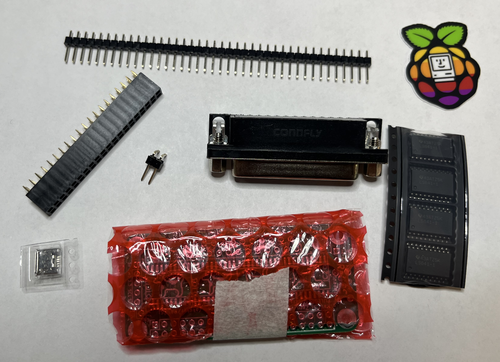
Regardless if you are building from a kit, or purchased your own parts, confirm you have the following components before assembly.
| Quantity | Image | Description | Link |
| 1 |
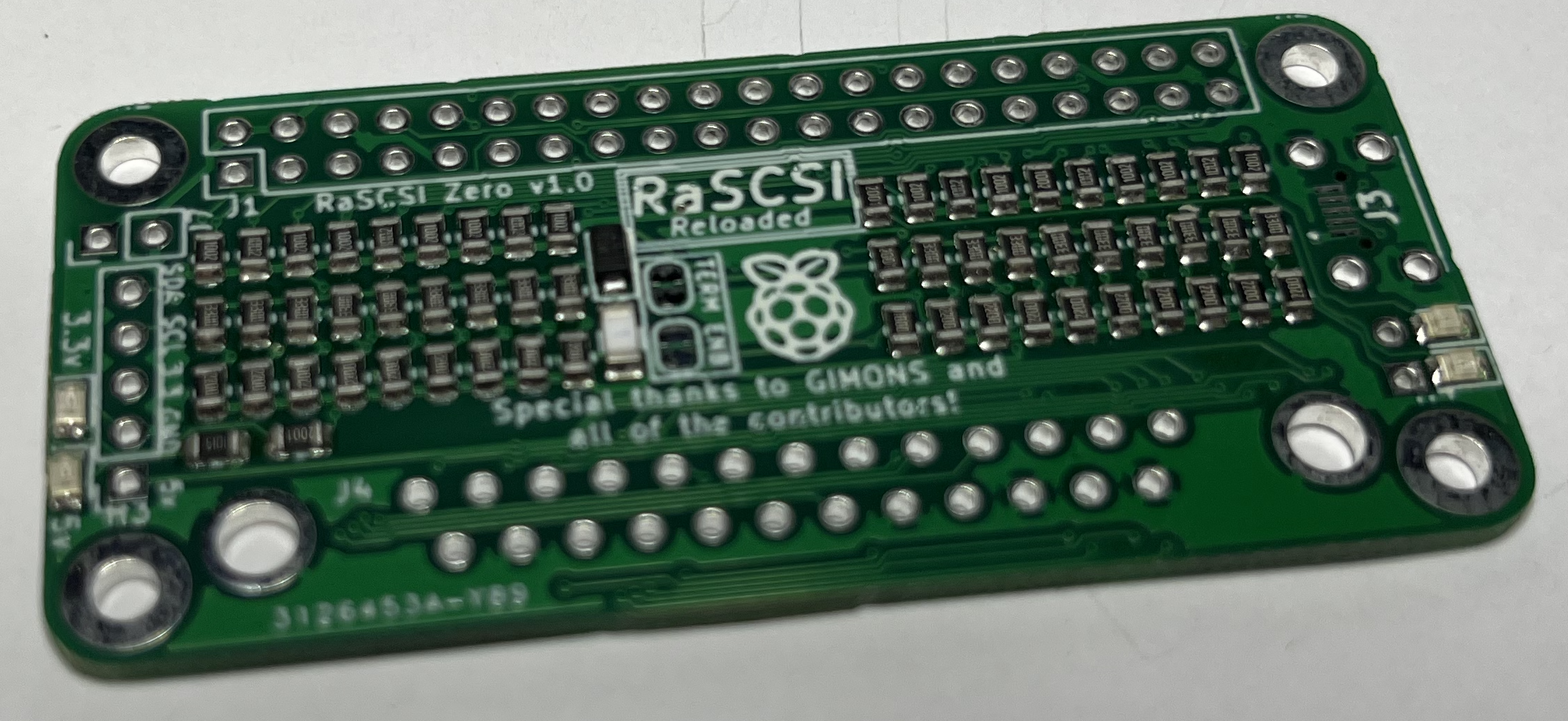
|
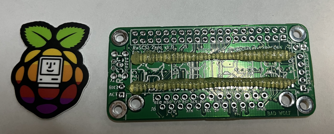
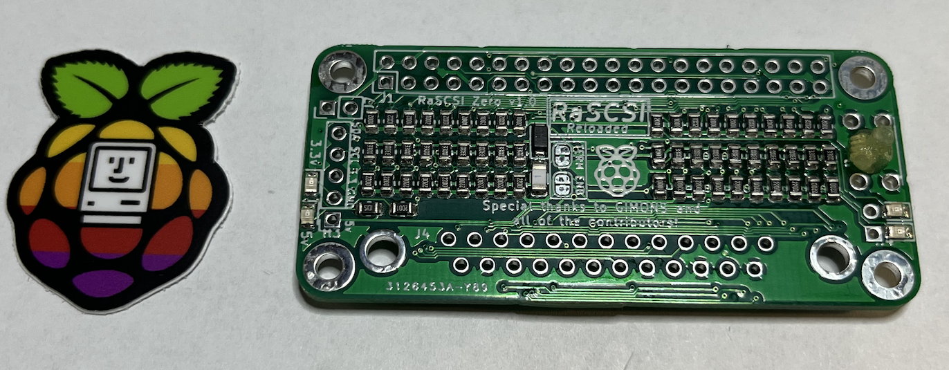
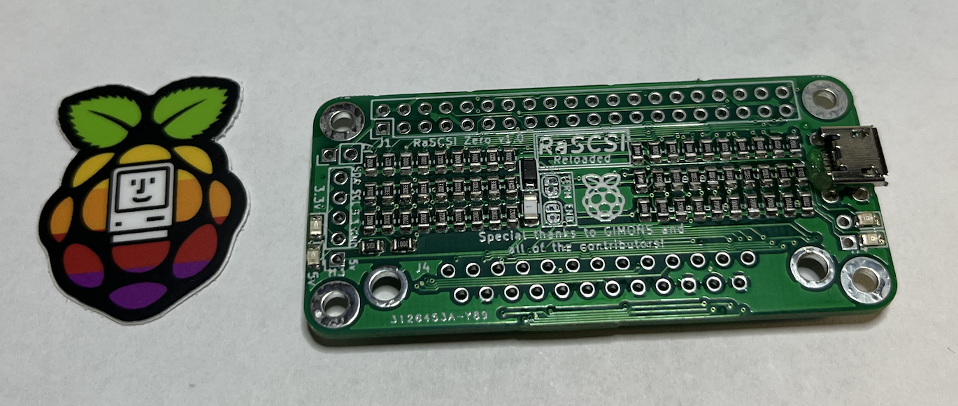
PiSCSI Zero Main Board with Resistors & LEDs pre-installed |
Tindie |
| 1 |
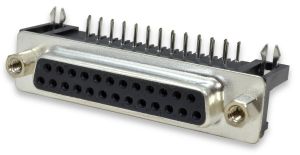
|
DB-25 Connector | LCSC |
| 4 |
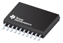
|
SN74LS641-1DW transceivers | Texas Instruments |
| 1 |
|
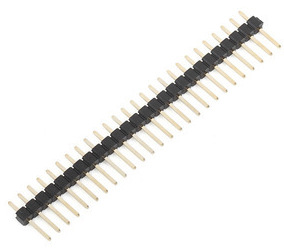
Breakaway pin headers | LCSC |
| 1 |
|
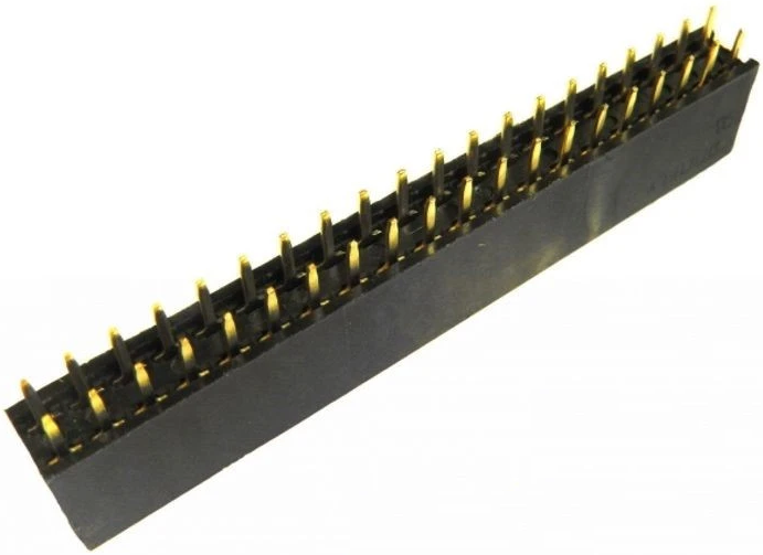
40-pin female header | LCSC |
| 1 |
|
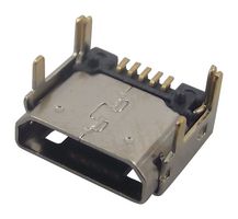
Micro USB connector | LCSC |
Please take careful note of the orientation of the PiSCSI Zero board, as well as the orientation of the Raspberry Pi Zero. If you assemble these incorrectly, DAMAGE MAY OCCUR!
The following section covers installing the transceivers.
|
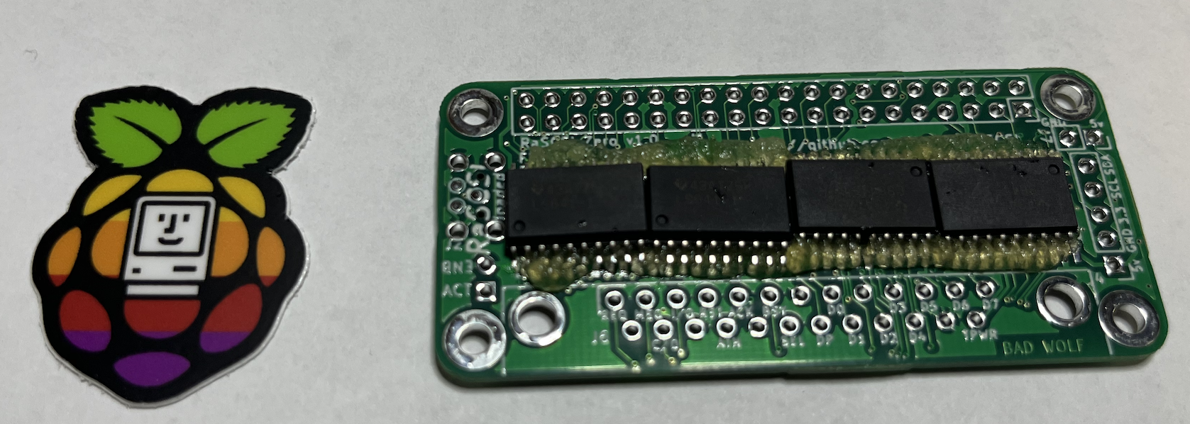
Note: Several people have had a common mistake while assembling their PiSCSI the first time. Please make a special note of the orientation of IC1 and IC2 vs IC3 and IC4 (the transceivers). Don't assume that they are all oriented the same way. Check that the dot on the chip (indicating pin 1) matches the circle on the board. |
|
|
Make sure the PCB is clean of debris. A quick wipe down with Isopropyl Alcohol 99% will work. Apply some flux to the transceiver pads. To speed the process up, you could apply flux to all pads to be soldered. This may speed up assembly. |
|
|
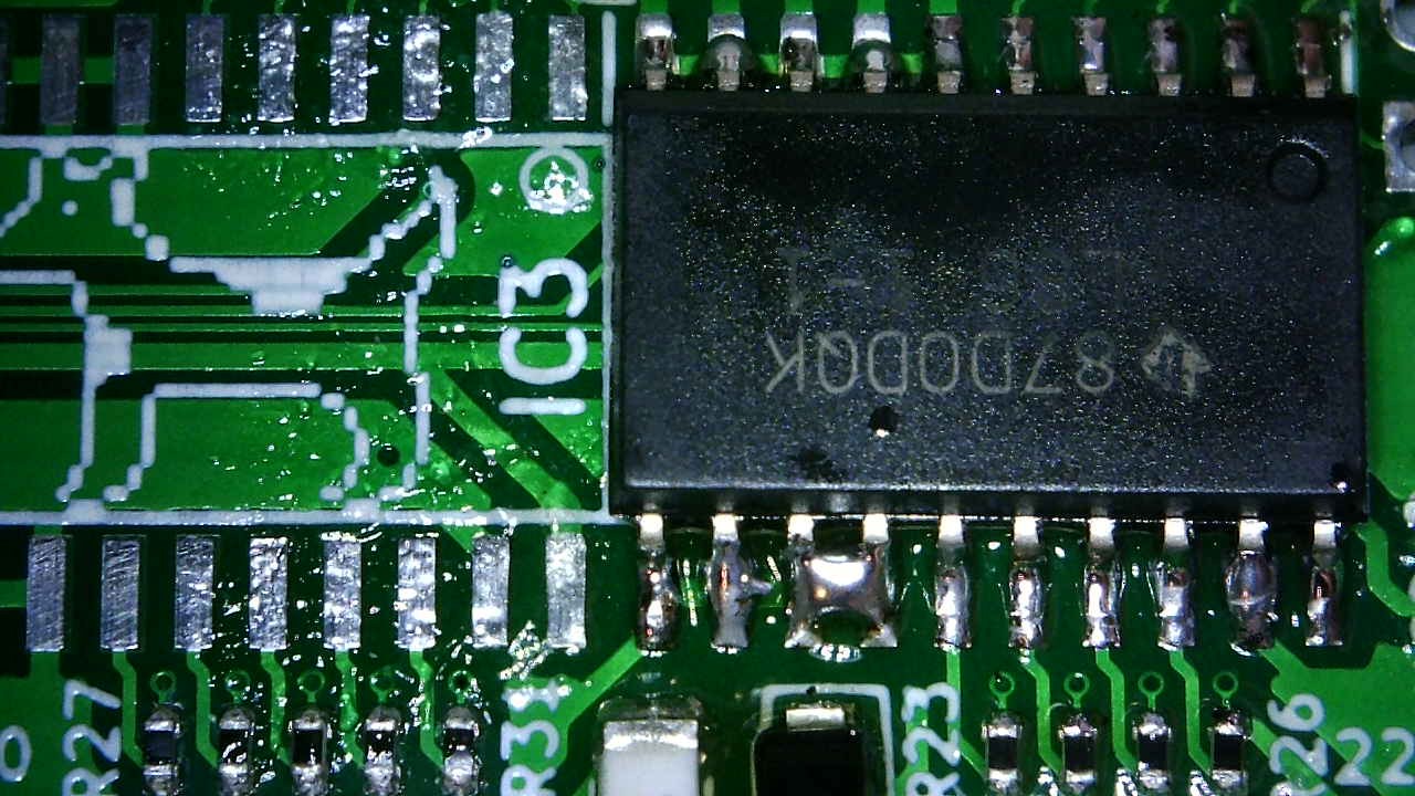
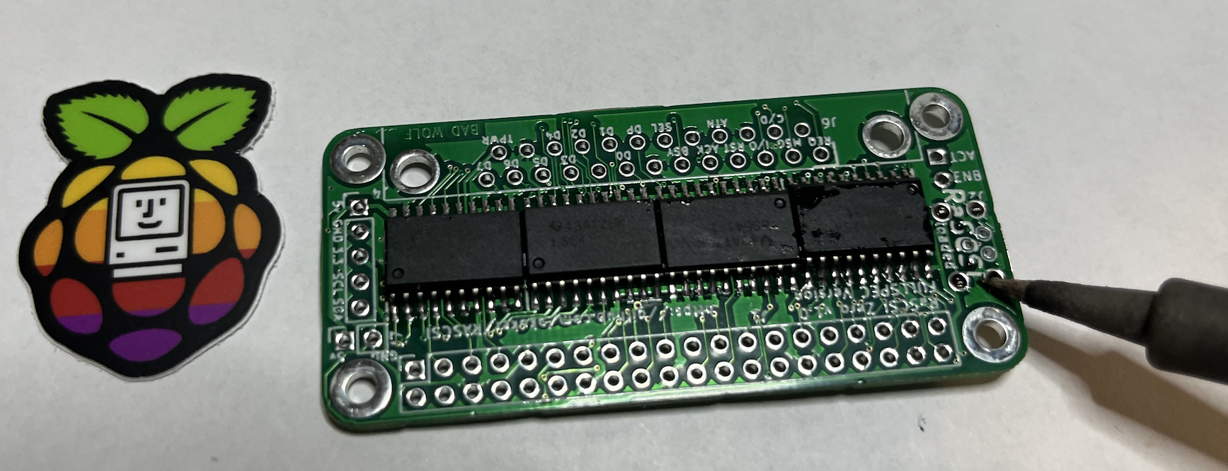
Place the transceivers, checking that the pins line up with the pads nicely. Note: Also ensure the dimple on the transceiver matches up with the circle on the silkscreen. This is discussed at the top of this section. |
|
| Solder the transceivers into place. If you're not familiar with surface mount soldering, there are several great demonstrations available on https://youtu.be/EW9Y8rDm4kE?t=374 YouTube |
|
| Before moving on, inspect your work for bridges between the transceiver pins. |
|
| Clean and prep the pads for the USB connector, and apply flux. |
|
|
Place the USB connector in the holes. The connector should also center the pins on the pads nicely. Solder the top pins in place. |
|
| And finally solder the bottom pins in place. |
|
| If you have a Raspberry Pi Zero WH (with headers), you will need to assemble your PiSCSI Zero differently. |

|
|
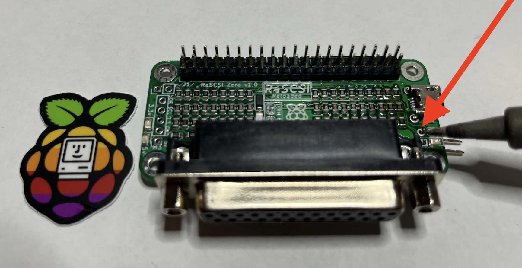
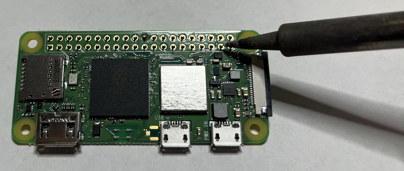
The most critical thing to check during assembly is that the pins are not reversed. A good way to check this is to verify Pin 1 on the PiSCSI connects to Pin 1 on the Raspberry Pi. Pin 1 has a square pad instead of circular. |
 
|
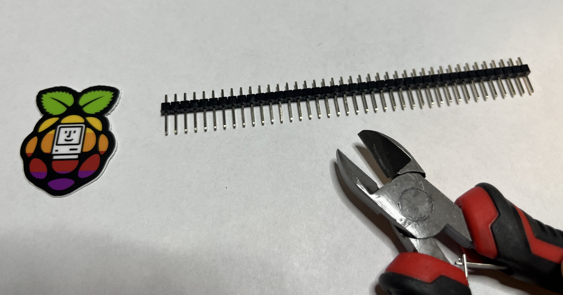
| Take the straight 40-pin breakaway header and cut it EXACTLY in half. You should end up with two headers that are 20 pins long. |
|
|
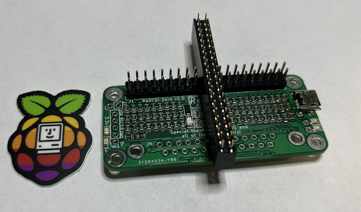
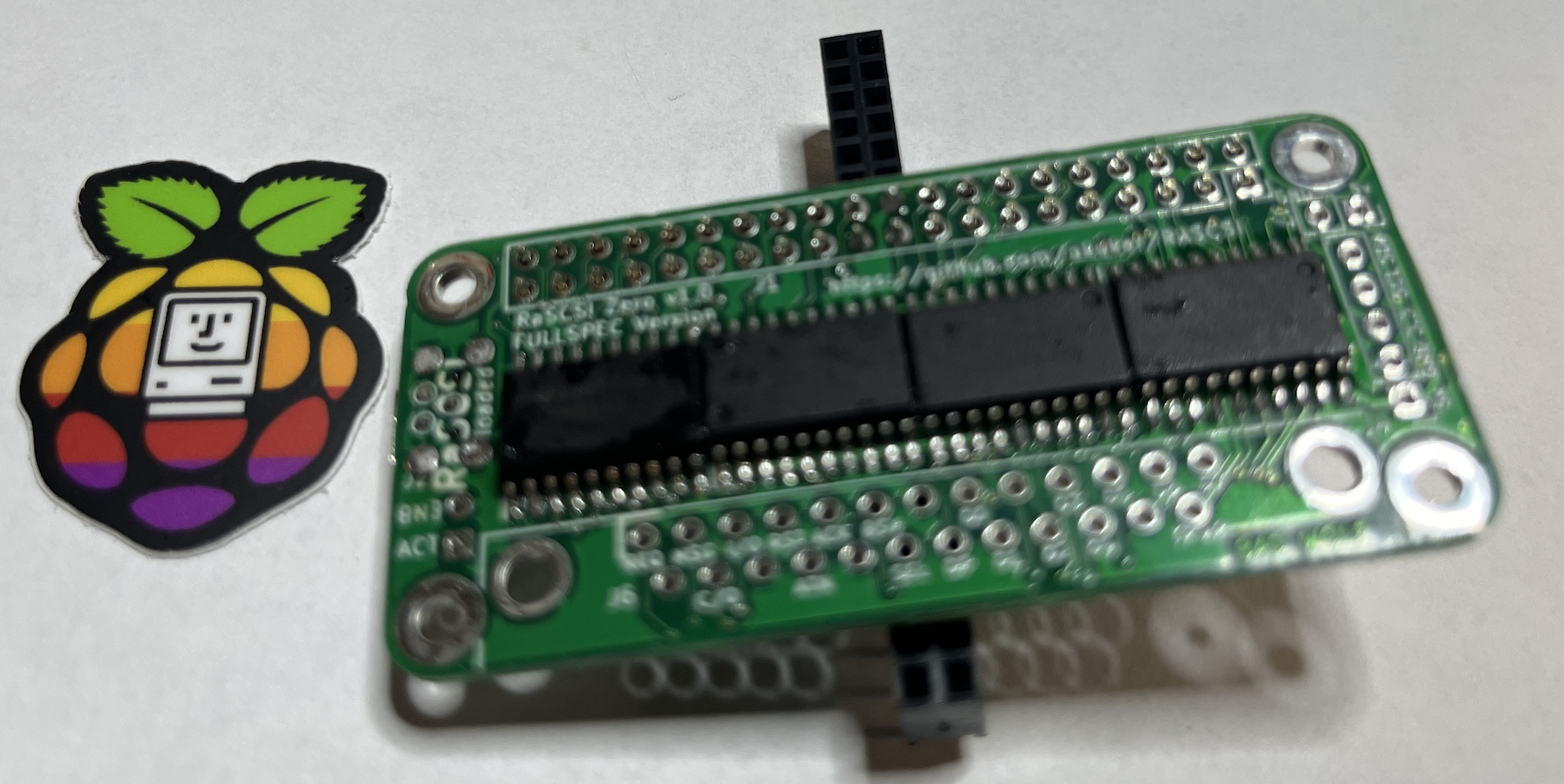
Insert the breakaway headers into the PiSCSI Zero board as shown here. Make sure you match the orientation of the board. The pins should point AWAY from the transceivers. Use the 20 pin female header as a guide to hold the male pins straight while you're soldering. |
|
| Flip the board and solder all of the male pins into the PiSCSI Zero board. You can remove the female header after a few pins are soldered in each row. |
|
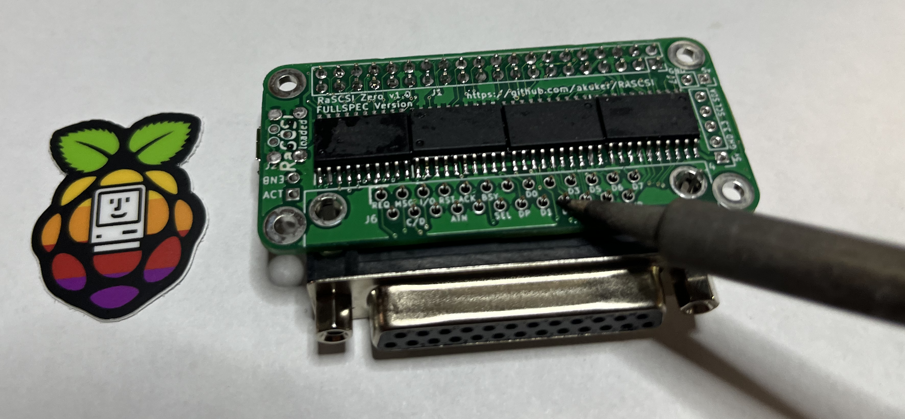
| Snap the DB-25 connector in the PiSCSI board. The mechanical clips should hold it in place. The DB-25 connector should be installed on the same side as the resistors. It should NOT be installed on the same side as the transceivers. |
|
| Solder all of the pins of the DB-25 connector |
|
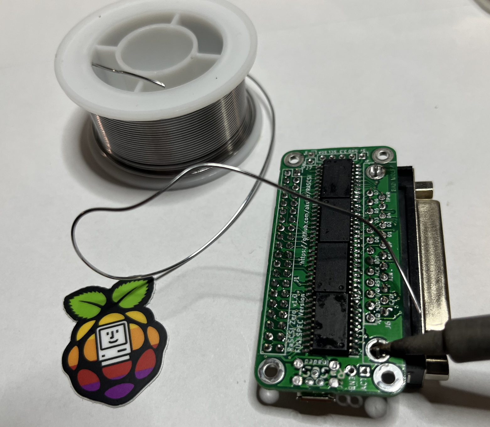
| Flood the mechanical standoffs with solder to re-enforce the DB-25 connector. Since there may be long cables attached to this connector, you want to have the additional mechanical strength. |
|
|
This step is OPTIONAL. You only need to install the 2-pin LED connector if you're using the PiSCSI Zero with an external LED. Insert the 2-pin right angle header into the holes, as shown. Solder these two pins into place. Tip: you can use the table to hold the right angle header in place (as shown here). Be careful not to touch the pins while soldering. They'll get VERY hot. |
|
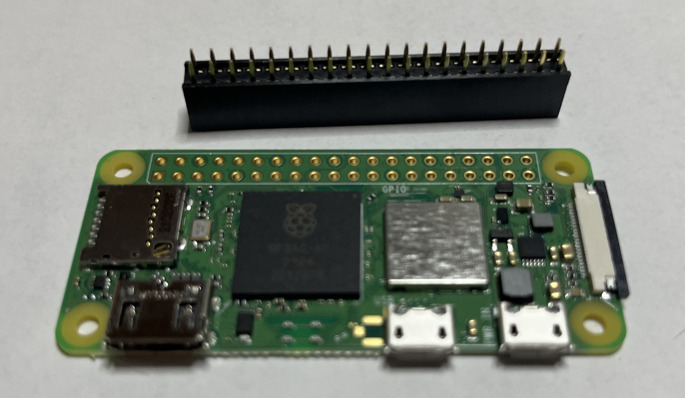
| Prepare your Raspberry Pi Zero, Zero W or Zero 2 W by making sure that the pads are clean. You may want to clean them with 99% Isopropyl Alcohol. |
|
| Next, you should solder the 2x20 pin female socket to the BOTTOM of the Raspberry Pi Zero. |
|
| You should now have the 2x20 pin female socket attached to the BOTTOM of the Raspberry Pi Zero. |
|
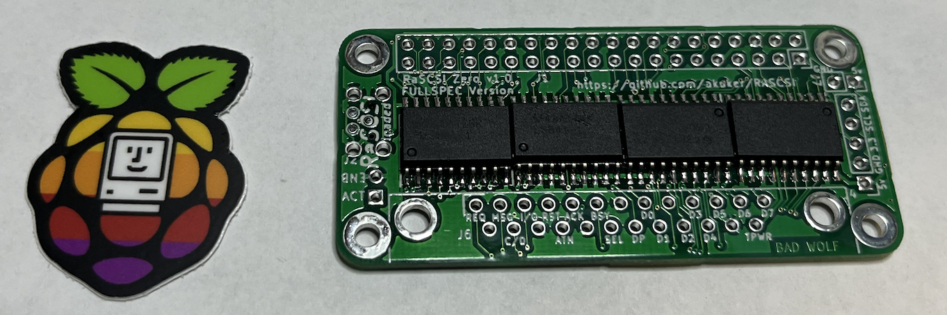
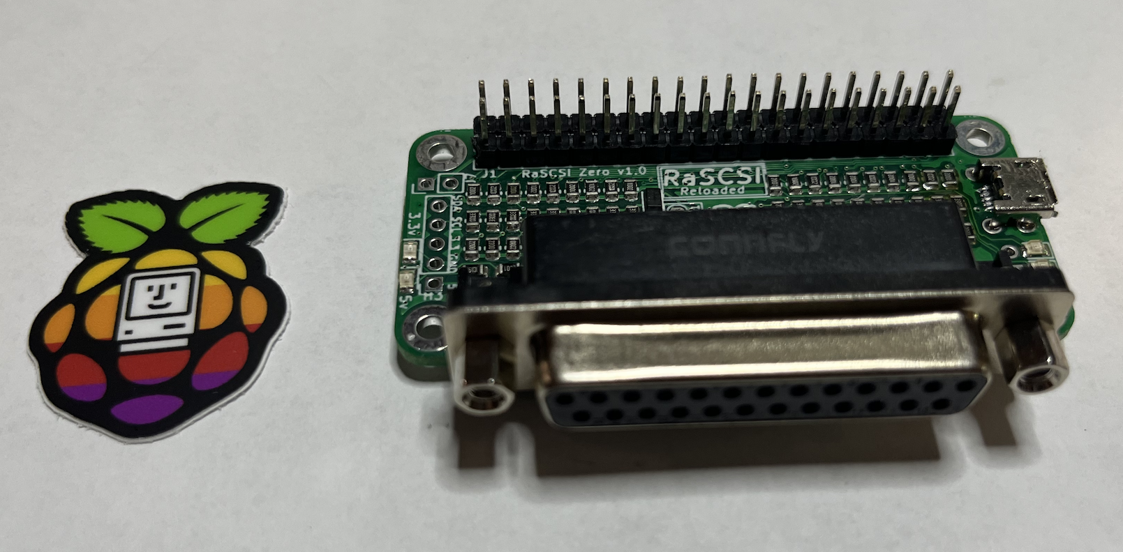
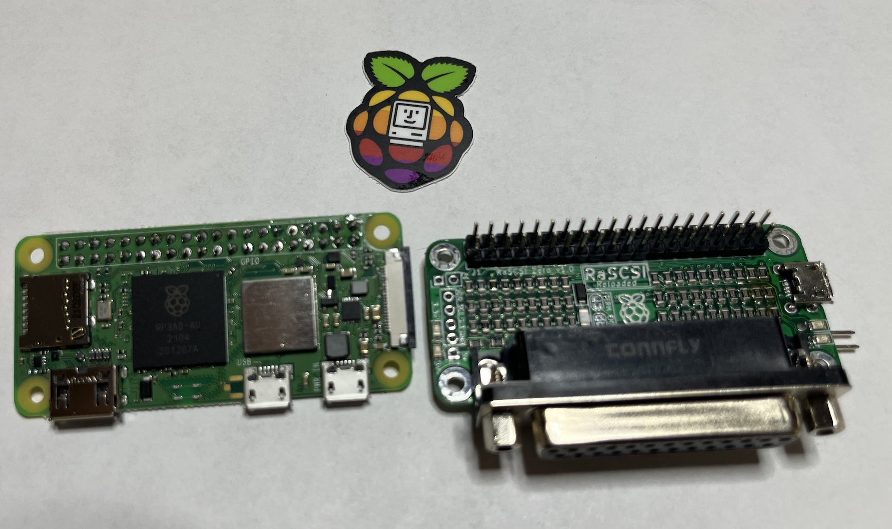
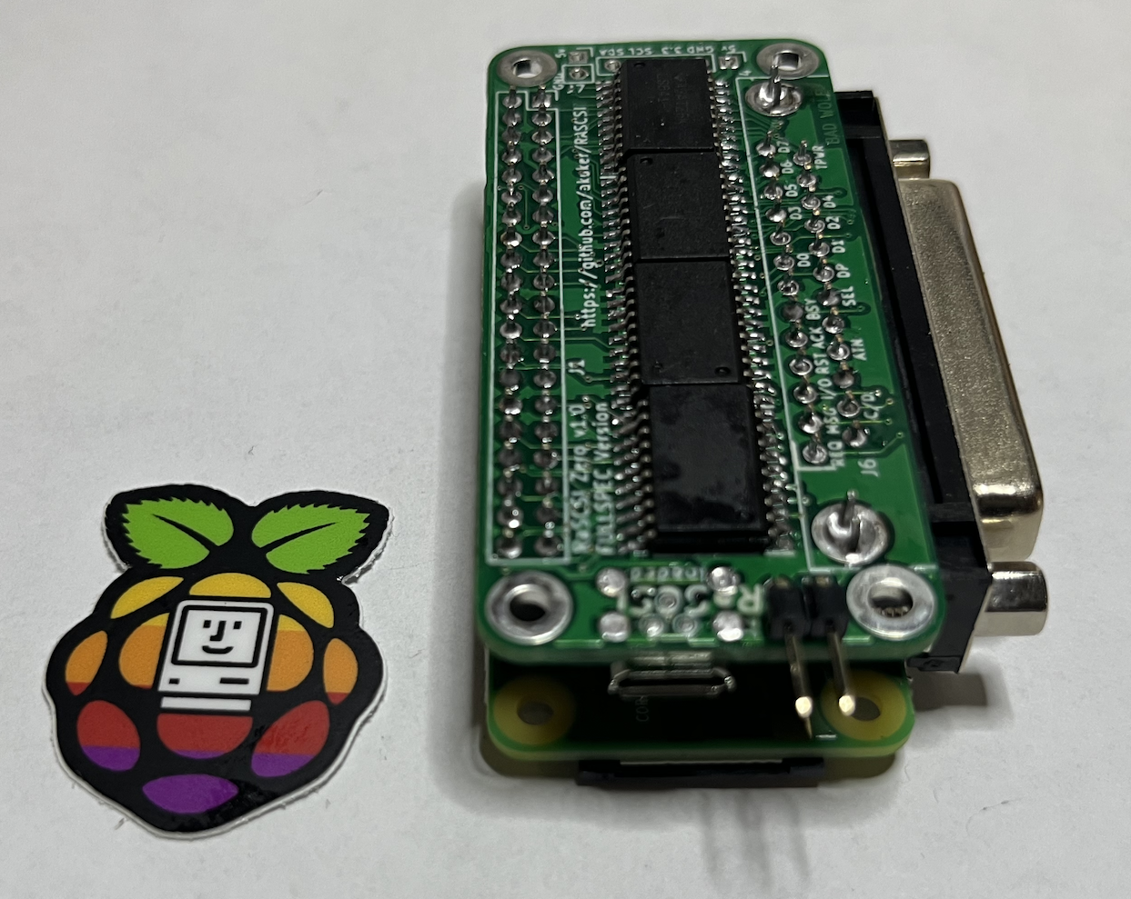
| You should now have a fully assembled PiSCSI Zero with the male pins on the same side as the resistors. Double check that your assembled pieces match this image. |
|
| You can now install the Raspberry Pi Zero on top of the PiSCSI Zero as shown here. |
|
| You can now continue with setting up the SD card and configuring your PiSCSI Zero! |

|
If you've gotten to this point, your PiSCSI board and optional daughter board are ready to use.
Proceed to the Setup Instructions page.