Full Size PiSCSI Assembly - PiSCSI/piscsi GitHub Wiki
If you are reading this page, it is most likely because you have purchased the PiSCSI kit (full sized version). Alternatively, you've ordered the PCBs and procured the parts to build the PiSCSI pHAT for your Raspberry Pi. Either way, the following instructions are provided on how to assemble your new PiSCSI Reloaded board.
Note that PiSCSI was originally called "RaSCSI Reloaded". There are no differences in the hardware between "PiSCSI Reloaded" and PiSCSI!.
If you have the PiSCSI Zero version, see the assembly instructions here
If you have not yet purchased one, you can pick up your very own PiSCSI Reloaded board on Tindie.
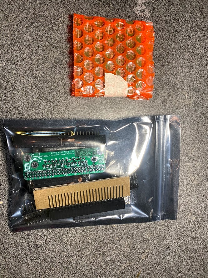
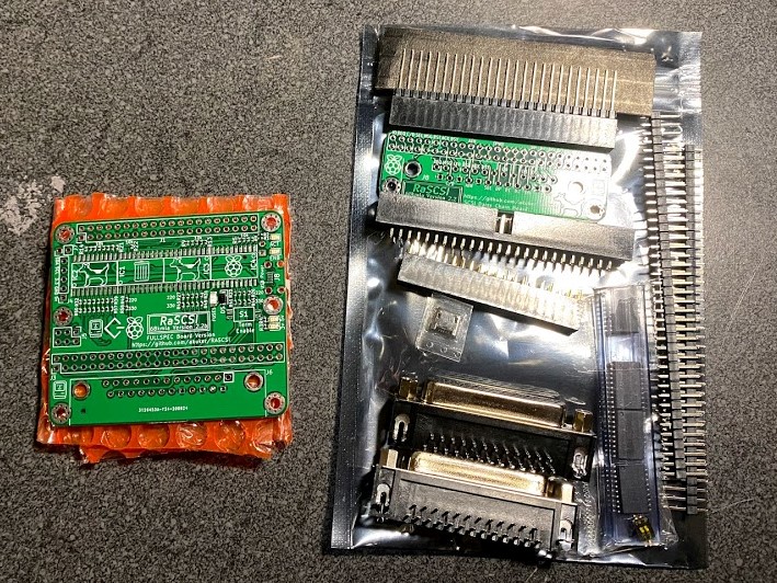
The PiSCSI kit available on Tindie contains everything you need to get going. In your package, you should see the following. Note that the Daisy Chain Daughter Board is an optional add-on. It might not be included in your order.
|
|
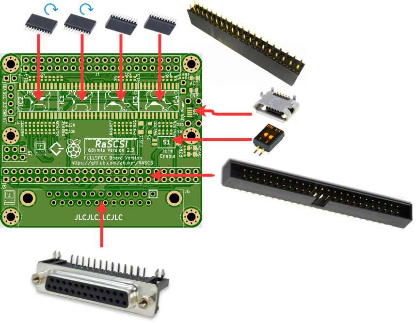
Regardless if you are building from a kit, or purchased your own parts, confirm you have the following components before assembly.
| Quantity | Image | Description | Link |
| 1 |
|
PiSCSI Main Board with Resistors & LEDs pre-installed |
Tindie |
| 1 |
|
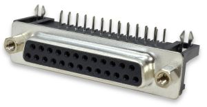
DB-25 Connector | LCSC |
| 4 |
|
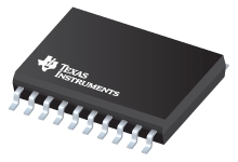
SN74LS641-1DW transceivers | Texas Instruments |
| 1 |

|
Surface mount switches | LCSC |
| 2 |
|
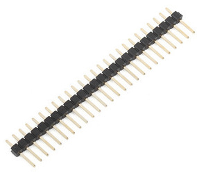
Breakaway pin headers | LCSC |
| 1 |
|
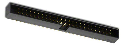
50-pin male box header | LCSC |
| 1 |
|
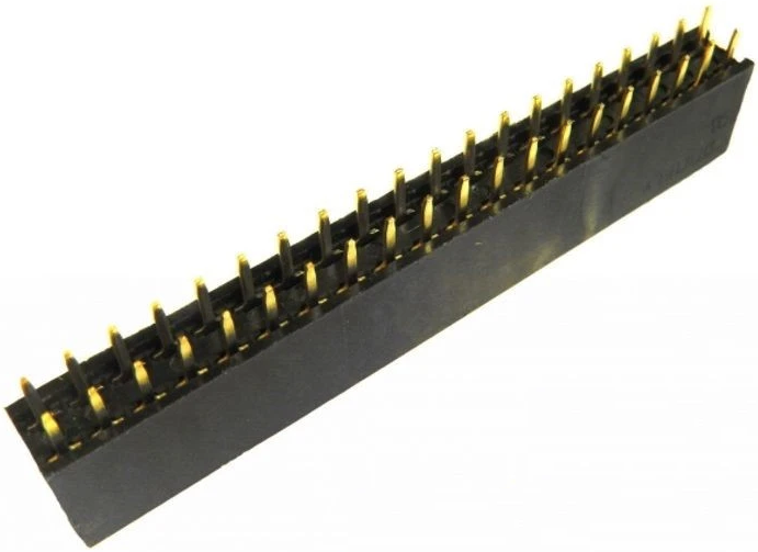
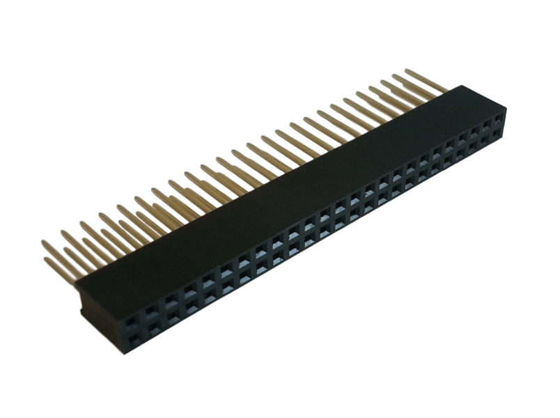
40-pin female header | LCSC |
| 1 |
|
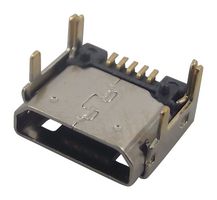
Micro USB connector | LCSC |
| Quantity | Image | Description | Link |
| 1 (Optional) |
|
PiSCSI Daisy Chain Daughter Board | Tindie |
| 1 |
|
DB-25 Connector | LCSC |
| 1 |
|
50-pin female header with extra long pins |
Aliexpress |
Mounting holes have been placed in the PiSCSI board to attach it securely to any of the supported Raspberry Pi models. M2.5 standoffs can be purchased to affix your PiSCSI to the Raspberry Pi from Amazon
A header is included for mounting an optional OLED screen to the PiSCSI board. The recommended OLED screen is MakerFocus SSD1306. Other models may be compatible, but this version has been tested with the python script included in the PiSCSI github repo.
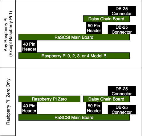
The PiSCSI Reloaded board has been designed to work with multiple Raspberry Pi models. With that, you have two options on how to attach the PiSCSI pHAT to the Raspberry Pi. This image shows these two options, one with the PiSCSI mounted above and the other showing the PiSCSI mounting below. Deciding how you want to orient your Raspberry Pi to the PiSCSI impacts which way you install the 50-pin female header listed under Kit contents. Note that, if you put the 40-pin header on the top of PiSCSI to accommodate a Raspberry Pi Zero: the pin headers for the Zero will need to be soldered to the bottom of the PCB (the pins should be on the side without the SD card/USB ports). This is not the typical location and, if you have a Zero WH model (with the header pre-soldered), the pins will be on the wrong side of the board. |
|
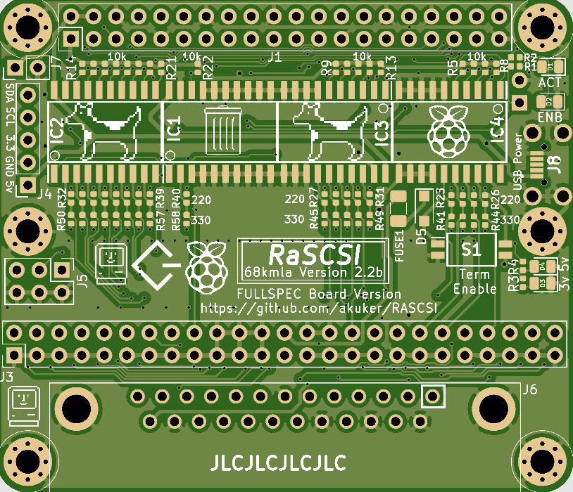
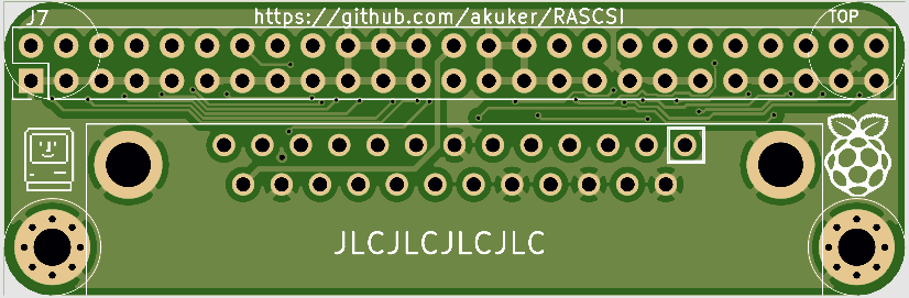
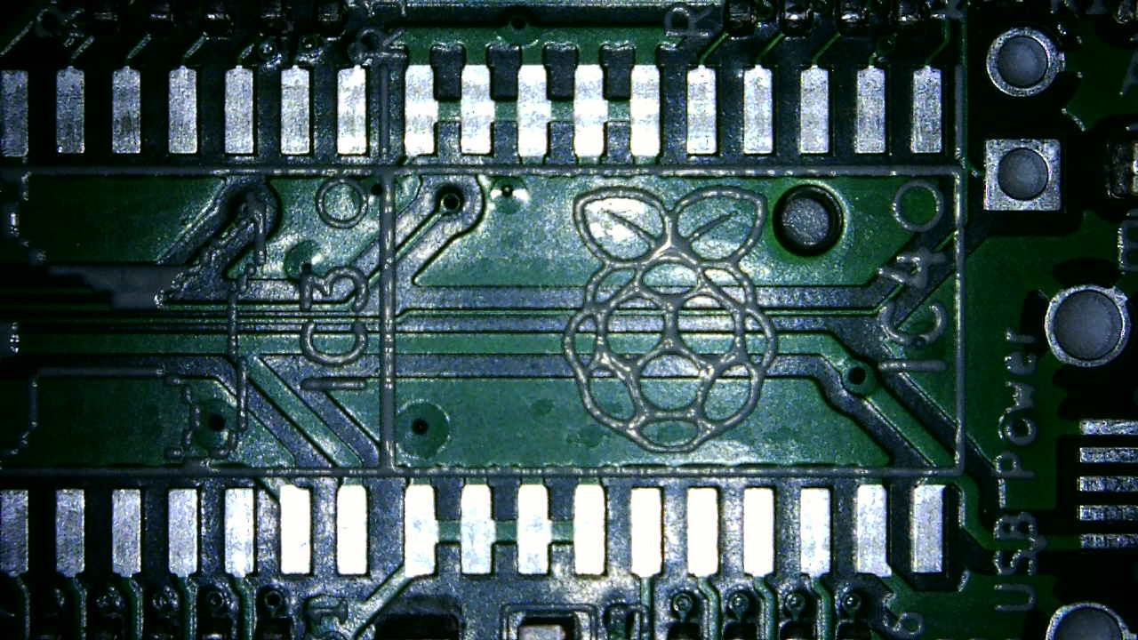
Before assembling, you should get familiar with the circuit board. This image shows some important connection points on the PiSCSI board. |
images/assembly/PiSCSI_Options.png |
As a general convention, the FEMALE socket is usually pointing down and the MALE pins are pointing up. |

|
This image shows all of the components we will attach to the main PCB. A good workflow when assembling electronics is to attach the smallest components first and finish up with the largest components. These instructions will follow that workflow. |
|
After receiving some feedback, it was determined to be easier to install the USB port first. By putting the USB port in place first, you have better access to the USB port pins for soldering. In the images below you will see the transceivers installed, but fear not, you will want to put the USB port on first, then install the transceivers, covered in the next step.
| Clean and prep the pads for the USB connector, and apply flux. |
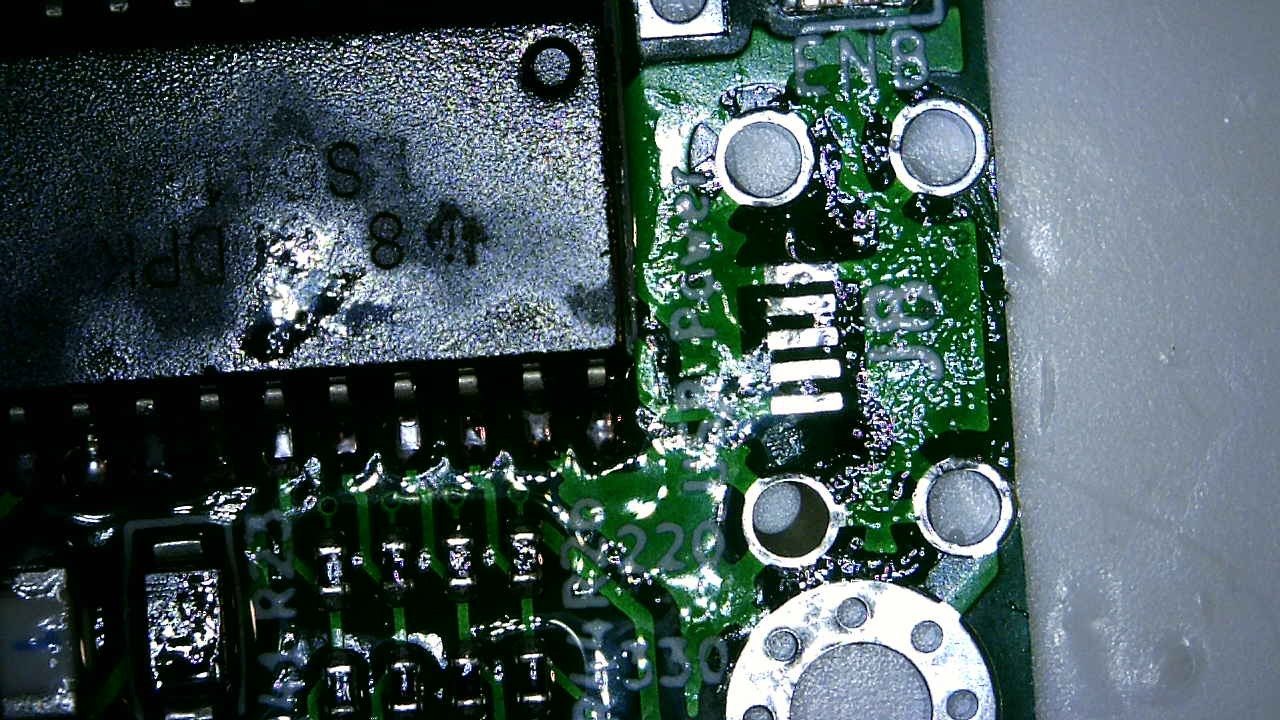
|
|
Locate the USB connector in the holes. The connector should also center the pins on the pads nicely. |
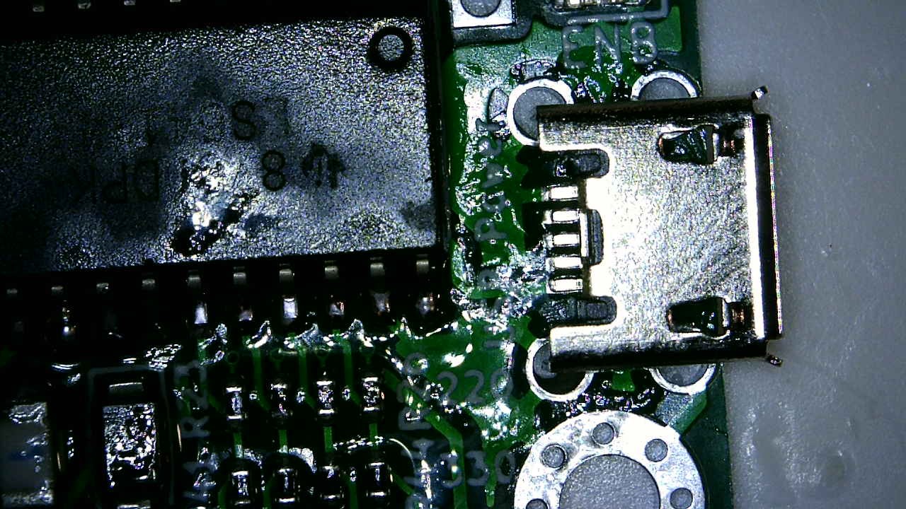
|
| Solder the top pins in place. |
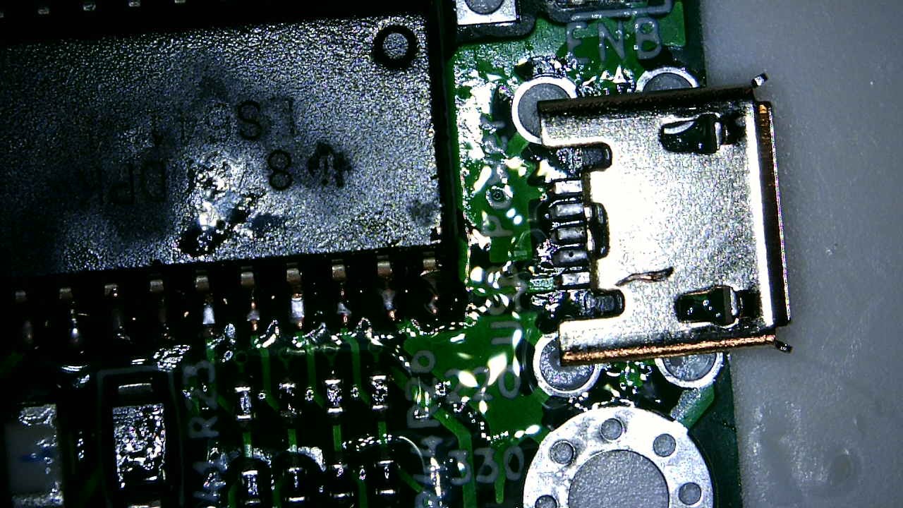
|
| And finally solder the bottom pins in place. |
|
If you're doing this assembly in order, the previous step covered installing the USB port. The following section covers installing the transceivers. The images show the USB port not installed. These pictures were taken before reorganizing the assembly steps, and you should have already installed the USB port.
|
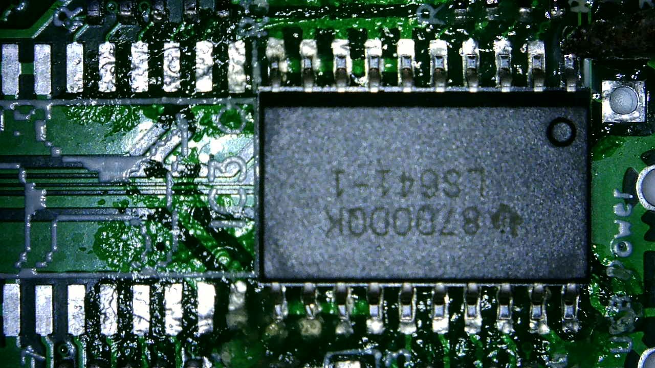
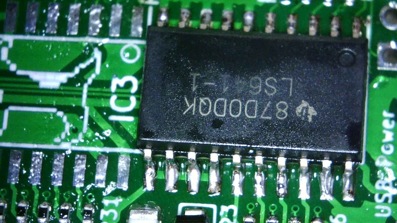
Note: Several people have had a common mistake while assembling their PiSCSI the first time. Please make a special note of the orientation of IC1 and IC2 vs IC3 and IC4 (the transceivers). Don't assume that they are all oriented the same way. Check that the dot on the chip (indicating pin 1) matches the circle on the board. |
|
|
Make sure the PCB is clean of debris. A quick wipe down with Isopropyl Alcohol 99% will work. |
|
| Apply some flux to the pads you're affixing the transceiver to. |
|
| An even coating is good. |
|
| To speed the process up, you could apply flux to all pads to be soldered. This may speed up assembly. |

|
|
Place the component, checking that the pins line up with the pads nicely. Note: Also ensure the dimple on the transceiver matches up with the circle on the silkscreen. This is discussed at the top of this section. |

|
|
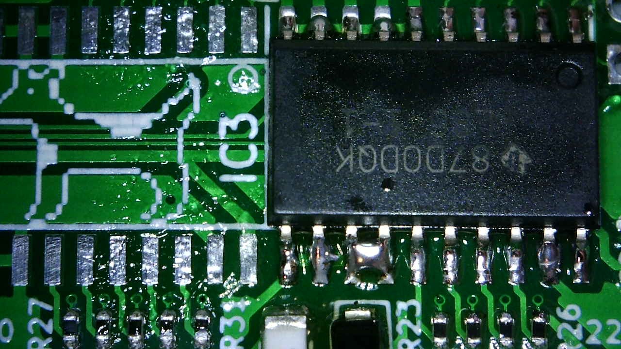
Tack two corners in place, and double check your alignment If everything looks good, solder the transceiver in place. This process requires very little solder. Loading up your tip or the pins with lots of solder will make extra work when you have to remove solder bridges. |
|
| Check all of your solder joints for bridges. |
|
|
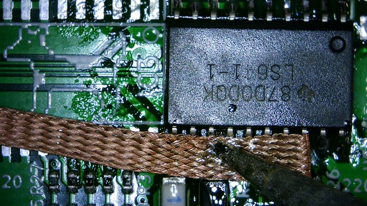
Use some solder braid or your favourite desoldering tool to remove the extra solder. |
|
| Check for any additional solder bridges and remove if necessary. |
|
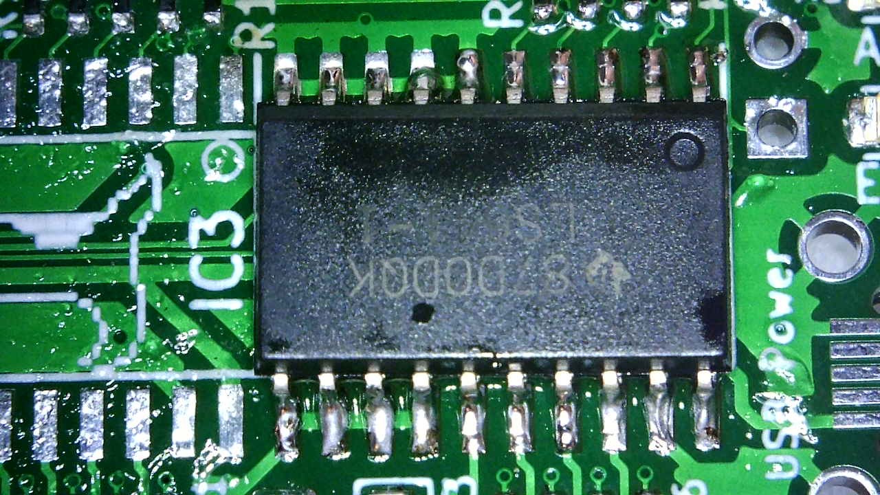
| Admire your handy work. Good job! |
|
With the first transceiver attached, do it three more times. But please please please heed the notice at the top of this section.
|
Clean the pads for S1 making sure there is no debris. Apply flux as you did when installing the transceivers. In this image, the flux is barely visible, almost like it's not there. |

|
| Locate the switch on the pads. and solder it in place. On should be facing the Raspberry logo. |

|
| You're doing great! Keep going! |
|
|
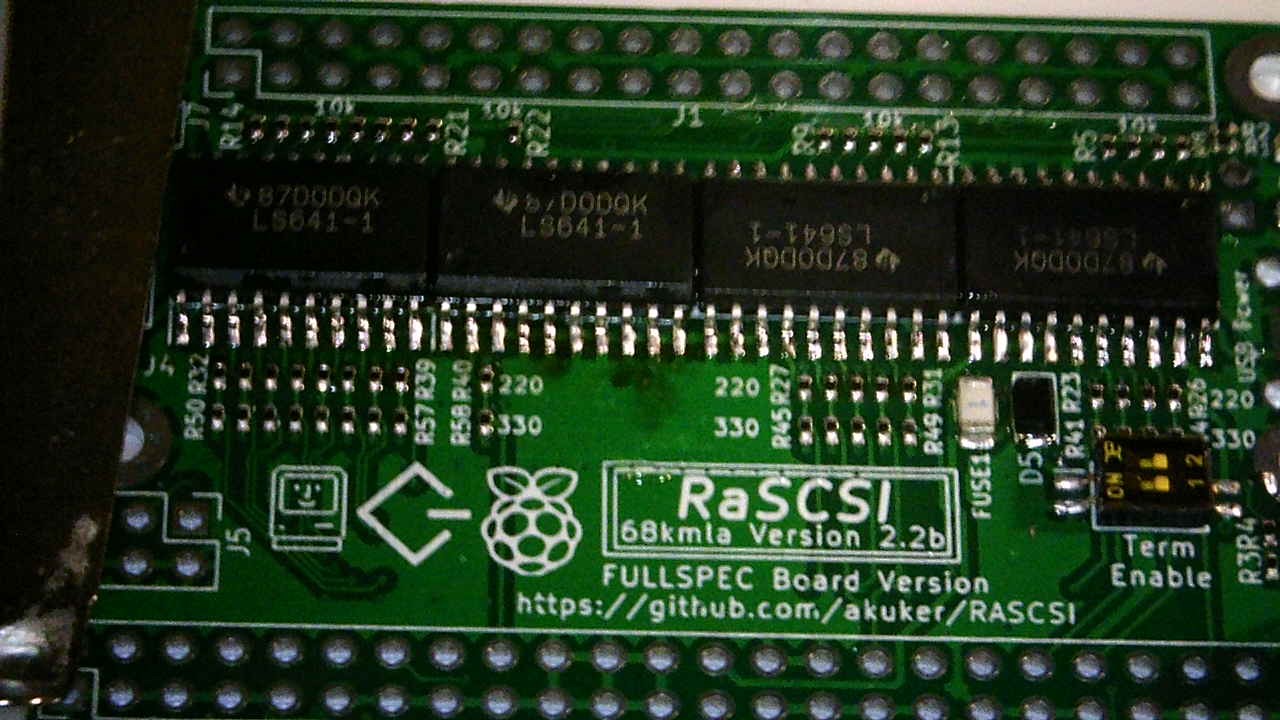
With the above components in place, you're on the home stretch. Check over the board for any solder bridges now, as they're easy to remove now then later when the unit gets plugged into your computer. The board should look similar to this. |
|
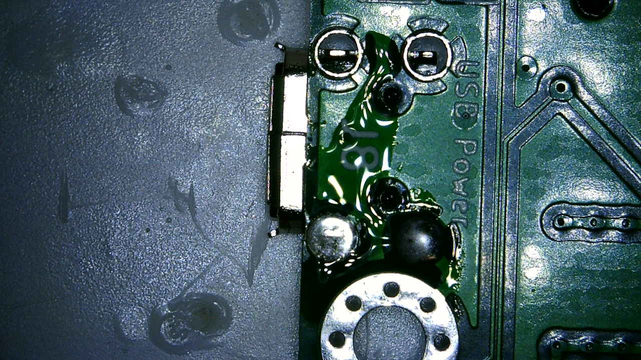
There is a potential issue with the PiSCSI (aka PiSCSI reloaded) board versions 2.4 and 2.5 when it is assembled with the DB-25 connector. If you are installing the DB-25 connector on your board, it is highly recommended that you make a small "cut" on your board. Over time, it appears that the DB-25 shield will wear through the solder mask and may come into contact with the 5v signal right below it. This essentially shorts 5v to Ground. Making this small cut will prevent this from happening.
https://github.com/piscsi/piscsi/issues/672
|
Use a razor blade or exacto knife to cut the copper trace under the green solder mask on the top of the PiSCSI board.
(Make sure there is no power applied to the PiSCSI board.) A short video on how to cut a trace on a circuit board is available here: https://www.youtube.com/watch?v=hT41OF4UX6Y |

|
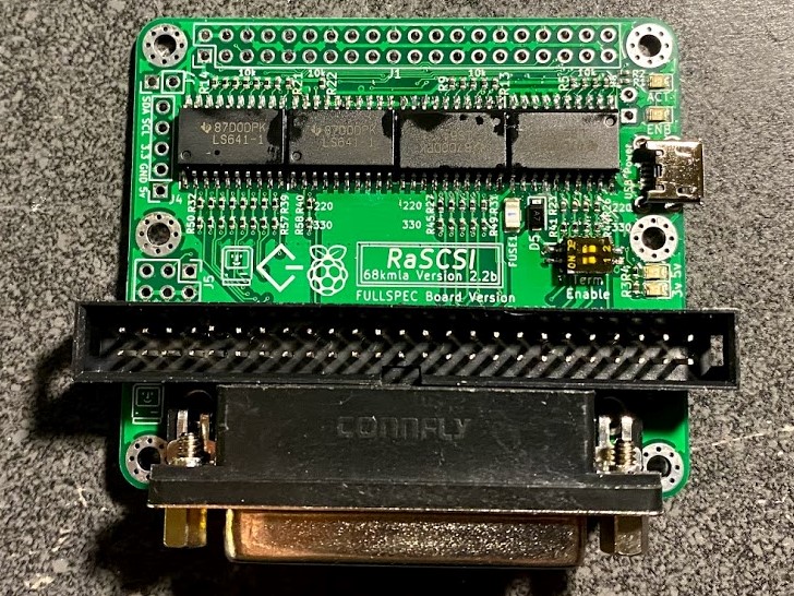
Now we proceed soldering up both the DB-25 and 50 pin SCSI connectors
|
Place the 50-pin male box header and DB-25 connector. Note: Be sure the key on the 50 pin connector faces the DB-25 connector. |
|
| And solder them in from the bottom. |

|
Note: This section is currently being populated
Note: This section is currently being populated.
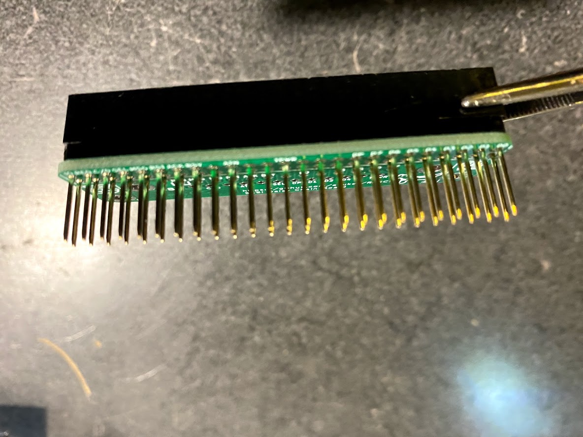
If your kit included, or you purchased it separately, the next steps cover assembling the Daisy Chain Daughter Board.
Note: You will find this next step easier if you install the 50 pin connector first, followed by the DB-25 connector. If you install the DB-25 connector first, it cramps the area you need to solder in the 50 pin connector. In the event you have already installed the DB-25 connector first, when you go to install the 50 pin header, first solder in the 'easy' row of pins, trim them to length, then solder in the remaining row of pins, and trim them.
Important: Before starting to solder the connectors, make sure the daughter board is in the right orientation, by looking at the silkscreen markings. The TOP side should be facing upwards, and the BOTTOM downwards.
| Place the female 50pin connector on the BOTTOM side of the daughter board and solder in place. |
|
| Once done, place the second DB-25 connector on the TOP side of the daughter board, and solder in place. |

|
| Once done, clip the extra pin length from the 50pin connector. |
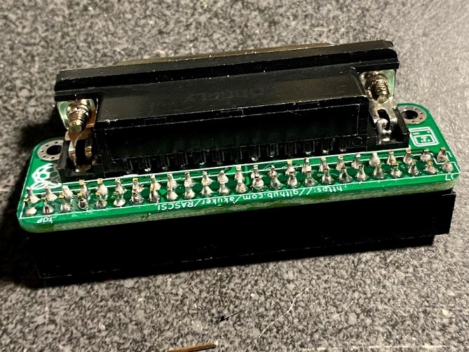
|
|
You're done! Do a quick test fit to make sure the daughter board attaches to the main board properly. In this example the pins were not trimmed. They were trimmed shortly after taking the picture. |

|
Note: This section is currently being populated.
If you've gotten to this point, your PiSCSI board and optional daughter board are ready to use.
Proceed to the Setup Instructions page.