Design - PetcuAlexandru/openpixi GitHub Wiki
This page should explain the design of some less trivial parts of OpenPixi. By "design" we mean the role of different classes and how they interact with each other. To express the design more concisely we use class diagrams with some basic UML language constructs. If you are new to class diagrams, do not worry and have a look on our short class diagram introduction. The class diagrams we use come in two flavors
- Simplified (black and white): These are by hand created simplified class diagrams which do not reflect the source code precisely. Their purpose is to give you a general idea of the design.
- Complete (colorful): These are generated by IDE and they precisely reflect the source code. Their purpose is to give you detailed design description.
The parts of OpenPixi which are introduced here follow
- Simulation Area Boundaries
- [Particle Boundaries Design] (#particle-boundaries)
- [Grid Boundaries Design] (#grid-boundaries)
- Particle and Cell Iteration (Parallelization)
Simulation Area Boundaries
When talking about the boundary of the simulation area we distinguish
- Particle Boundaries (PB): Determine how does the particle behave when it crosses the simulation area.
- Grid Boundaries (GB): Determine what value is retrieved when we ask for a cell outside of the simulation area.
Currently, two types of PB and GB are supported
-
Hardwall Boundaries
- In PB case the particles are reflected from the edge of the simulation area
- In GB case there is a special stripe of extra cells around the whole simulation area which can be used to interpolate to and from.
-
Periodic boundaries
- In PB case the particles reappear at the other end of the simulation area.
- In GB case if we ask for a cell which is outside of the simulation area on the left side we get a cell from within the simulation area on the right side.
Particle Boundaries Design
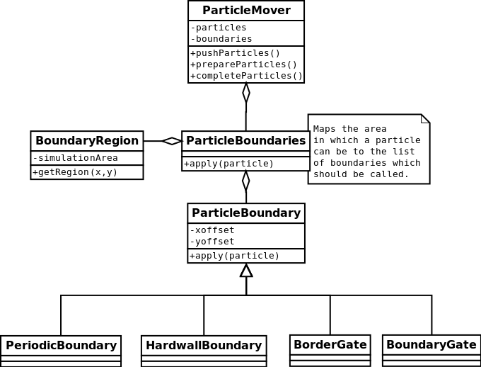
A simplified design of the particle boundaries is revealed in the class diagram below

A short explanation of how the particle boundaries work follows
- The boundaries are applied in the
ParticleMover.push()method. - First, we **determine the region in which the particle is **(
BoundaryRegion.getRegion()). There are 8 boundary regions (regions outside of the simulation area) in which we are interested. - Afterwards, we call a boundary class which is responsible for the particles in the identified region.
By splitting the area outside of the simulation area to regions we can have different boundary types at different sides of the simulation. While this is unnecessary in the non distributed version, it is an essential concept in the distributed version where it allows us to use a special kind of particle boundaries (BorderGate and BoundaryGate) which take care of particles exchange between two nodes.
The complete class diagram which also includes the particle boundaries for the distributed version can be found here.
Grid Boundaries Design
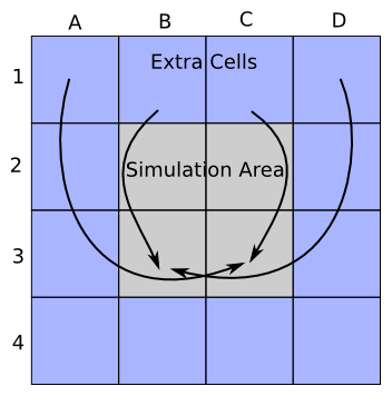
The grid consists of a two dimensional array of cells. For the cell we have a simple class. The difference between hardwall and periodic boundary is implemented quite differently from the particle boundaries. With the grid boundaries we have a stripe of extra cells around the simulation area. These extra cells are used in field solving and in for allowing interpolation of particles which are close to the simulation area edge. The difference between hardwall and periodic boundary is in the cell references in the stripe of extra cells.
As the picture below suggests under the periodic boundaries the stripe of the extra cells actually references the cells from inside the simulation area. In the picture we show where the references of only the top extra row point.

Under the hardwall boundaries the stripe of the extra cells references new cells. It is questionable whether a solution where we have different number of cells allocated is the best as the number of places where we have to take the difference explicitly into account grows.
Particle and Cell Iteration (Parallelization)
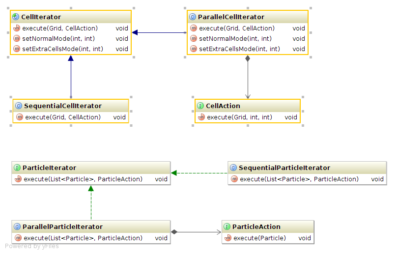
There are many places in the OpenPixi application where we can take advantage of multi-core processors and use multi-threaded parallelization. Basically, in each of the four main simulation steps (push particles, interpolate to grid, solve fields and interpolate to particle) we iterate either over all the particles or over all the cells. These iterations can be done sequentially or in parallel using two and more threads. The design of the sequential and parallel iteration is shown in the diagram below

Any code which needs to iterate over particles or cells can take advantage of the above iteration classes to gain a parallel implementation. The code only needs to implement the ParticleAction or CellAction interface which defines the operation the code wants to execute upon each Particle or Cell. Once that is done the code can simply call the execute() method of the iterator and pass the implemented action as parameter. For a specific example you can take a look at ParticleMover class.
Since in each of the four simulation steps one can choose from different algorithms it is essential to decouple the iteration over the particles or cells from the actual algorithm.