Representations of Electronics - PatternAgents/Electronics_One_Workshop GitHub Wiki
-
We use different representations of electronic systems for different purposes, to convey various types of information quickly and efficiently.
-
An engineer will begin with just a rough "Block diagram" sketch of a complete system, and then refine that "Block diagram" as design decisions are made, and individual components are selected.

- That is usually followed by a more detailed diagram that shows individual components, known as a Schematic, or Schematic Diagram. A Schematic, or Schematic Diagram is a representation of the elements of an electronic system using abstract, graphic symbols rather than realistic pictures. A schematic usually omits all details that are not relevant to the information the schematic is intended to convey, and may add unrealistic elements that aid in comprehension or in conveying the essential “design intent”

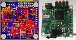
- The final physical representation, known as the Layout, is typically in the form of an etched, Printed Circuit Board which connects all the physical components together, usually with melted metals, known as Solder, during fabrication.

The process of converting from a Schematic representation to a Layout Representation is usually done with a Computer Aided Design package, such as EagleCad, which has a free student version.
The Electronics Schematic is your Route Map
- Sometimes it is easier to think of an electronics schematic diagram as a map for the electrons, it describes where they will go, and the "stops" along the way

- We can read a schematic diagram just like our Bus Route map, as the electrons must follow the wires, just like the Bus must follow the Route map. Of course, you've likely seen electrons go "off-roading" - anytime you've seen an electric spark. But they usually stay on the Bus, and follow the Route map (the wires) in most situations.
Different Strokes for Different Folks
As you encounter more electronics circuits and schematic diagrams, you will start to see there are many different writing styles, just like writing prose (or writing computer code). There are many different styles, from basic sketch to highly pictorial. It's often a matter of your personal style, and how you want to tailor the diagram to reach your audience. There are, of course professional standards and International Standard Organization standard symbols for precise international communication, but for your own projects, you can use any style that works for you.
