Passive Circuits - PatternAgents/Electronics_One_Workshop GitHub Wiki
Passive Circuits are those that only consume energy, and are incapable of providing gain or amplification. A circuit that can generate energy, or provide gain or amplification is known as an Active Circuit.
Resistors
We have talked biefly about the Resistor {R}, a passive circuit component.
The schematic symbols for various resistor type are shown below:

This Resistance Simulator Applet will allow you to visualize changing voltage, current and resistance, with an Alternating Current input.
Wire
Well, what about wire you ask? Isn't the conductor itself considered a component? Sure it is, and when it gets long enough it begins to add resistance as well. But for now, we'll consider our wire to be "perfect" in order to simplify our circuit analysis. The schematic symbol for wire is just a "line":

Capacitors
A Capacitor is a passive two-terminal electrical component that stores electrical energy temporarily in an electrostatic field. The forms of practical capacitors vary widely, but all contain at least two electrical conductors (plates) separated by a dielectric (i.e. an insulator that can store energy by becoming polarized). The schematic symbol for a capacitor is:

Since a Capacitor has an insulator in the middle, it is essentially an open-circuit to Direct Current, and so, we can use a Capacitor to block Direct Current and to only allow Alternating Current to pass.
When it comes to Direct Current, think of a Capacitor as Gandalf, "You Shall Not Pass!". Where Alternating Current is concerned, the Capacitor is more friendly.
This Capacitance Simulator Applet will allow you to visualize changing voltage, current and resistance, with an Alternating Current input.
Inductors
An Inductor is a passive two-terminal electrical component which stores Energy in a magnetic field. As the current through the Inductor changes, the strength of the magnetic field changes:

It consists of a conductor such as a wire, usually wound into a coil shape. Energy is stored in a magnetic field in the coil as long as the current flows. When the current flowing through an inductor changes, the time-varying magnetic field induces a voltage in the conductor, according to Faraday’s law of electromagnetic induction. The schematic symbol for an Inductor is:

Inductance, the ratio of the voltage to the rate of change of current, which has units of henries (H). Inductors have values that typically range from 1 µH (10−6H) to 1 H. Many inductors have a magnetic core made of iron or ferrite inside the coil, which serves to increase the magnetic field and thus the inductance.
This Inductance Simulator Applet will allow you to visualize changing voltage, current and resistance, with an Alternating Current input.
Transformers
A Transformer is an electrical device that transfers electrical energy between two or more circuits through electromagnetic induction. Electromagnetic induction produces an electromotive force across a conductor which is exposed to time varying magnetic fields. Commonly, transformers are used to increase or decrease the voltages of alternating current in electric power applications. The schematic symbols for various transformers are shown below:

Diodes
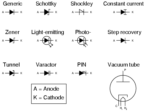
A Diode is a two-terminal electronic component that conducts primarily in one direction (asymmetric conductance); it has low (ideally zero) resistance to the flow of current in one direction, and high (ideally infinite) resistance in the other. A semiconductor diode, the most common type today, is a crystalline piece of semiconductor material with a p–n junction connected to two electrical terminals.
The schematic symbols for common diodes are shown below:

Passive Circuits
Just as before we could wire our batteries in Series or in Parallel, now we have a number of passive components we can wire together, such as the Series RLC Circuit shown below :

This Series RLC Simulator Applet will allow you to visualize changing voltage, current and resistance, with an Alternating Current input. Or try this Circuit Simulator

This Parallel RLC Calculator Applet will allow you to try out different component values and alternating current frequencies.
We're not going to get too deeply into circuit analysis or Kirchhoff's laws, that is beyond the scope of this simple introduction, we will cover those concepts as they are needed.
Next ->
======================== Further (Links)