Logic Circuits - PatternAgents/Electronics_One_Workshop GitHub Wiki
Analog or Digital
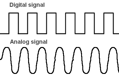
Up to now, we have been talking primarily about Analog Signals, or signals that vary their Voltage or Current over Time. The wires to your headphones are an example of Analog Signals, namely, the Right and Left Analog Audio Channels for your headphones.
Digital Signals are said to one of two states, either "On"(True) or "Off"(False), in contrast to Analog Signals, that have many states. The USB cable you use for you phone, or keyboard, or mouse are examples of Digital Signals.
Digital Logic Gates
Digital Logic Gates are primarily implemented using diodes or transistors acting as electronic switches, but can also be constructed using vacuum tubes, electromagnetic relays (relay logic), fluidic logic, pneumatic logic, optics, molecules, or even mechanical elements. A logic gate is an elementary building block of a digital circuit.
Logic circuits include such devices as multiplexers, registers, arithmetic logic units (ALUs), and computer memory, all the way up through complete microprocessors, which may contain more than 100 million gates. In modern practice, most gates are made from field-effect transistors (FETs), particularly MOSFETs (metal–oxide–semiconductor field-effect transistors).
An individual function is referred to as a Logic Gate because the output is "gated" or determined by some logical combination of the inputs. For example, an AND gates output is True only if ALL of it's inputs are True, but an OR gates output is True if ANY of it's inputs are True.
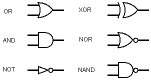
We summarize the operation of Logic gates in something known as a "truth table", the equations of which can be solved using Boolean Algebra

Multiplexors (Selectors)
A multiplexer (or "mux") is a device that selects one of several input signals and forwards the selected input into a single output. In the olden days, a switchboard operator would manually connect two telephone line together on a patch panel, today that work is all done automaticlly using multiplexors. Multiplexers are mainly used to increase the amount of data that can be sent over a wire within a certain amount of time and bandwidth. A multiplexer is also called a data selector, or selectors, since they select one input to be routed to one output. There are a number of different multiplexer types, both analog and digital only multiplexers, as well as bidirectional (current can flow in either direction) and unidirectional (current can flow in only one direction) multiplexers.
An electronic multiplexer makes it possible for several signals to share one wire or resource, for example one A/D converter or one communication line, instead of requiring one wire per input signal path.

Demultiplexers (Decoders)
A Demultiplexer (or Decoder) is the opposite of a multiplexer, demultiplexers take one data input and a number of selection inputs, and they have several outputs that the input signal can be routed to, based on the selection inputs. Demultiplexer forward the data input to one of the outputs depending on the values of the selection inputs.

Logic Thresholds (What is True?)
All Digital Signals are actually Analog Signals also, it is just that there is some agreement as to what Voltage range constitutes "ON" or True, and which Voltage range constitutes "OFF", or False. These Voltages are referred to as the Threshold Voltages, and you will see them abbreviated on data sheets as things like Vil and Vih (the Voltage Input considered to be Low "0", and the Voltage Input considered to be High "1"). That is the difference you will see between different logic families, like CMOS, Low Voltage CMOS, TTL, etc. , what voltages they operate on (3.3 volts of 5 volts) and what Voltages are considered to be "ON' and "OFF". It is also the reason we often have to use level translation circuitry when going from 3.3 Volt logic to 5.0 Volt logic, they can have different viewpoints on what constitutes True and False...
Three State Logic Gates
Three-States you say? "ON", "OFF", and ?
The third state is "Not Driven". Normally to get an "ON" or an "OFF" one output needs to be active and "driving" that wire. Well, how about if it disconnects from the wire completely? We call that a "third-state", also know as "Tri-State". Three-State Logic allows an output port to assume a high impedance state in addition to the 0 and 1 logic levels, effectively removing the output from the circuit. The control pin of a three-state gate is refered to as the "enable"(EN) pin or "Output Enable"(OE) pin on most devices.

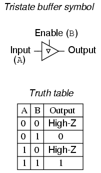
When the the "enable"(EN) pin or "Output Enable"(OE) pin is inactive, then the Gate output is disconnected. In order to signify this state, we use "High-Z", or just "Z", to indicate the "Not-Driven" state,
Three-State Multiplexer
Now that you know how Three-State Logic works, you can see how we can make a multiplexer using Three-State Logic

This is an important concept in modern embedded electronics, as it is an inexpensive way to share wiring (or pins).
Open-Collector Logic
Three-State Logic enabled us to have several different circuits sharing the same wire, by disconnecting all other circuits but the one allowed to use it. Open-Collector Logic also allows several outputs to share the same wire, but it's more of "party line" since they are all talking at once. A typical example of an Open-Collector Logic is the Inter-Integrated Circuit Bus, or I2C bus, commonly used in embedded electronics for connecting integrated circuits together.
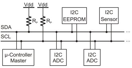
The way that Open-Collector Logic works, is that a Resistor is used to "Pull-Up" the bus to a high voltage (or "on" or a "1", or "True") when no devices are active. Any device on the bus can activate it's Open-Collector Output to pull the bus to a low voltage (or "off" or a "0", or "False").

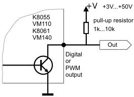
Think of it as the pull chain on the bus to indicate to the driver that you want to get off at the next stop, any passenger can pull the chain to request a stop. Open-Collector Logic is just like that.
Storage The Flip-Flop
By configuring two transistors in a cross wired topology, we can make a circuit that "sticks" in the "On" or "Off" state, which means it remembers it's state, and can act as storage. This is the basis of all memory systems.
Flip-flops and latches are used as data storage elements. A flip-flop stores a single bit (binary digit) of data; one of its two states represents a "one" and the other represents a "zero". Flip-flops can be either simple (transparent or opaque) or clocked (synchronous or edge-triggered). Usually we use the term flip-flop for discussing clocked circuits; the simple Flip-flop types (transparent one) are commonly called Latches.
Sequential or Clocked Logic
An Asynchronous circuit, is digital logic circuit which is not governed by a clock circuit; the signals "Flow" from input to output according to their own timing. A Synchronous circuit, on the other hand, is a digital logic circuit which is governed by a clock circuit; and signals can change state only after a "tick" of the clock has elapsed.
Sequential logic is used to construct finite state machines, a basic building block used in all digital circuitry, as well as memory circuits. Virtually all circuits in modern devices are a mixture of combinational and sequential logic.
The schematic symbol for the "D" Type Flip Flop:
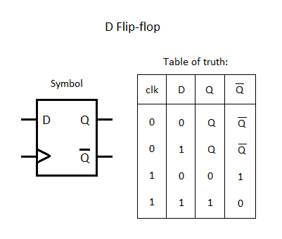
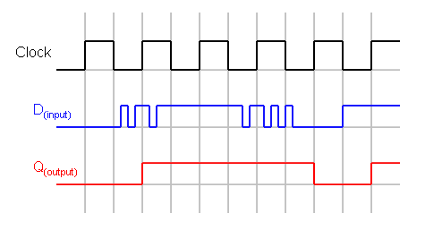
You'll see that the Input (D) is only "sampled" when the clock transitions from a Low Voltage(0) to a High Voltage (1) and effects the Output (Q). The transitions on the Input(D) that are a higher frequency than the Clock are lost.
Frequency Division and Counting
One of the things we can do with Flip-Flops and Sequential Logic, is to make counters and dividers. For example, if we feedback the output of the flip-flop to itself, we can cut the clock frequency in half.

Similarly we can chain Flip-Flops together to make counters and dividers of any number of bits.
Complex Logic Gates
Given the above simple logic gates, (i.e. NAND, NOR, or AND,OR, and NOT), you can make every function that you might ever want. But Integrated Circuits began to get more specialized, in order to make them smaller and more power efficient, so more Complex Logic Gates were designed. These include components like, adders, subtractors, arithmetic logic units (ALUs) and more.
7400 Logic
The 7400 series was one of the earliest standardized Integrated Circuit families for designing computers; it contains hundreds of devices that provide everything from basic logic gates, flip-flops, and counters, to special purpose bus transceivers and arithmetic logic units (ALU). These chips were the basis for some of the first computers.
The early 7400 Logic series components were designed using BJTs, with later families (i.e. 74C00) changing to MOSFETs for lower power usage. There are now a wide variation of 74xx and 54xx families, including 74BCT00 and 74ABT00, which are both a BICMOS process (Bipolar Transistors and MOSFETS together).

Your PALS, GALs, and PLAs
There are a number of different programmable logic device families, allowing the user to "craft" their own hardware by programming the device to function as desired. Internal Fuses (curved lines) are "blown" to program the device to a specific function.
Field Programmable Gate Array
A field-programmable gate array (FPGA) is an integrated circuit designed to be configured by a customer or a designer after manufacturing – hence "field-programmable". The FPGA configuration is generally specified using a hardware description language (HDL), similar to that used for an application-specific integrated circuit (ASIC).
Application Specific Integrated Circuit
An application-specific integrated circuit (ASIC), is an integrated circuit (IC) customized for a particular use, rather than intended for general-purpose use. For example, a chip designed specifically to run in a digital voice recorder or a high-efficiency Bitcoin miner is an ASIC.
Next ->
==========================