Input Output Circuits - PatternAgents/Electronics_One_Workshop GitHub Wiki
- A computer system is not very much use unless we can get data in and out of it. We do that with General Purpose Inputs and Outputs (GPIO), which allow us to interact with the outside world.
Ports and Pins
-
A General Purpose Inputs and Outputs (GPIO) port is a group of GPIO pins (typically 8 GPIO pins) arranged in a group and controlled as a group.
-
Again, different families, or manufacturers can name them differently, PORT A, PORT B, etc. or PORT 0, PORT 1, etc. So in some microprocessor families you will see PORTA_0 or PORTA_7 (PORT A bits 0 and 7, respectively) and on others you might see PORT0_0, or PORT0_7 to indicate the exact same thing.
Pin Modes - In or Out?
- On most modern microprocessors, the pins can share a number of functions, they can often be Analog, Digital, or one of several dedicated functions, like USB or Serial. Inside the Microprocessor address space, we have locations for Control Registers that control the operation of the device pins, which the microprocessor can write into, and change the pin's hardware configuration.
- The Pin Mode register of a pin determines what (internally to the microprocessor) connects to that pin. The Pin Mode register of a pin determines whether that pin acts as an input or an output or as some other function. These information in these registers is often organized differently for different chip families (i.e. AVR vs. Cortex, vs. PIC, etc.).
- The Arduino IDE takes care of those differences for you internally, so you generally don't have to worry about it.
Pull-Up / Pull-Down
-
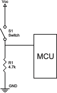
Most General Purpose Inputs and Outputs have the ability to enable an internal pull-up resistor, internal pull-down resistor, or both. This allows us to use a simple switch or push-button to provide an input control to the microprocessor.
-
Because it is normally pulled-up by a resistor, the pin (#0 in this case) will read as a "1", until it is pressed by the user, then it will read as a "0".
pinMode(0, INPUT_PULLUP);
switch = digitalRead(0);

-
Not all chips or devices include a pull-down resistor option (AVR doesn't), but it looks like this:
pinMode(0, INPUT_PULLDOWN);
switch = digitalRead(0);

Output Pins
-
If we want to drive an external signal, we should set our pin mode as "OUTPUT".
pinMode(9, OUTPUT);
digitalWrite(9, LOW);

Analog Pins
-
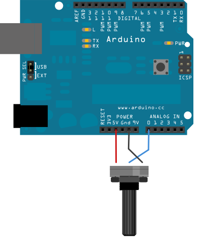
Depending on which Microprocessor family you are using with the Arduino, you will have one or more Analog-to-Digital Converter channels, named as A0 though A15. These pins can also be used as Digital Inputs or Outputs, but usually not at the same time (pick on). When acting as an Analog Pin, the pinMode is set to INPUT.
pinMode(A0, INPUT);
analog_in = analogRead(A0);

Next
==========================