Converter Circuits - PatternAgents/Electronics_One_Workshop GitHub Wiki
- There are many ways of measuring, controlling, and representing physical quantities, like temperature, air pressure, humidity, and the like. Sometimes these quantities are in an Analog representation, a continuous-time variation of voltage or current coming out of a sensor; and we need to get that data into the computer somehow. That is when we use an Analog-to-Digital Converter to convert the analog domain into the digital domain.
ADC
-
An Analog-to-Digital Converter (ADC, A/D, or A to D) is a device that converts a continuous physical quantity (usually voltage) to a digital number that represents the quantity's amplitude.
-
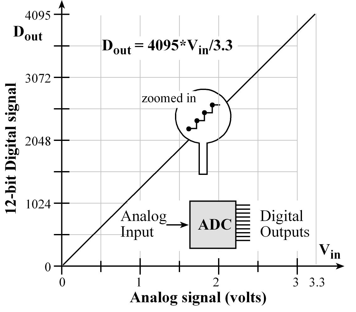
The conversion involves quantization of the input, so it necessarily introduces a small amount of error. The ADC does this conversion periodically (its take some time), sampling the input instead of continuously performing the conversion. The result is a sequence of digital values that have been converted from a continuous-time and continuous-amplitude analog signal to a discrete-time and discrete-amplitude digital signal.

- The above example is a 12-bit Analog-to-Digital converter, which produces numbers from 0 to 4095. So, when the input is at 3.3 Volts the ADC will return a result of 4095. When the input is at Zero (0) Volts, the ADC will return a result of 0.
There are many considerations when choosing or using an ADC component, with the most significant ones typically being resolution (how many bits of precision), and the sampling rate (how many ADC samples per second), other considerations are power and accuracy.
The schematic symbol for an ADC
-
In the Arduino IDE, the Analog-to-Digital Converter can have several channels, starting from A0, up to the maximum number of channels (A5-A15), depending on the microcontroller device family. The ADC channels are accessed using the "analogRead" method.
pinMode( A0, INPUT);
ADCchannel_0 = analogRead(A0);
/* ... */
pinMode( A15, INPUT);
ADCchannel_15 = analogRead(A15);
ADC DELSIG Type
-
Delta-Sigma Analog-to-Digital Converter (or sometimes called Sigma-Delta) modulation ADC is a type of converter that converts the Analog input into a pulse frequency; is is also known as Pulse Density modulation or Pulse Frequency modulation.
-
The Delta-Sigma Analog-to-Digital Converter converts the mean of an analog voltage into the mean of an analog pulse frequency and counts the pulses in a known interval so that the pulse count divided by the interval gives an accurate digital representation of the mean analog voltage during the interval. This interval can be chosen to give any desired resolution or accuracy. The method is cheaply produced by modern methods; and it is widely used for lower sampling rate Analog-to-Digital Converters.
ADC SAR Type
- A Successive Approximation Result ADC is a type of analog-to-digital converter that converts a continuous analog waveform into a discrete digital representation by performing a binary search through all possible quantization levels before finally converging upon a digital output for each conversion. It is much faster (and uses more power) than a DELSIG ADC.
DAC
The Digital-to-Analog Converter or DAC for short, is the opposite of the ADC; it takes a digital number as input and outputs a Analog signal, either Current or Voltage.

The schematic symbol for the Digital-to-Analog Converter is shown below (it's the ADC symbol reversed...)

-
In the Arduino IDE, the Analog-to-Digital Converter can have several channels, starting from A0, up to the maximum number of channels (A5-A15), depending on the microcontroller device family. The ADC channels are accessed using the "analogRead" method.
pinMode( A0, OUTPUT);
analogWrite(A0, value0);
/* ... */
pinMode( A15, OUTPUT);
analogWrite(A15, value15);
Control Systems
Analog-to-Digital Converters and Digital-to-Analog Converters are key to putting together real-time Control Systems. This allows us to sample a sensor and control an output in response to changes in the sensor input.

Next ->
==========================