AC DC - PatternAgents/Electronics_One_Workshop GitHub Wiki

No, not that AC~DC, I'm talking about Alternating Current and Direct Current.
-
In our examples up to now, we have only considered Direct Current. which is current moving in only one direction along the wire, from positive to negative, just like a car battery. However, the current can also reverse direction along a wire, and then we call it Alternating Current.
-
For example, in the U.S.A., the Alternating Current that we get from our domestic wall sockets reverses direction with a frequency of sixty (60) times every second, all day long. We refer to that as 60 Hertz Alternating Current
-
We refer to current that reverses polarity with a regular periodicity as Alternating Current, if it is not regular, we refer to it as Pulsating, or just variable current.
Types of Current Flow
- When looking at a Waveform plot, like the one below, you will see the magitude (either Current or Voltage) on the Y-Axis and the passage of Time on the X-Axis
- You will see that the green Alternating Current waveform above is a Sine, or Sinusoidal Waveform. Most power systems attempt to provide pure sine waves for powering equipment.
Listen to a 220 Hertz Sine Wave
- There are many other types of Alternating Current (or A.C.) Waveforms other than the Sine Waveform
- One key to understanding electronics is learning how different Alternating Current Waveforms are used for different purposes, like powering things, controlling things, and making sounds.
- We'll show how all of these different Waveforms can be generated using a circuit or a small microcontroller like an Arduino.
Duty Cycle
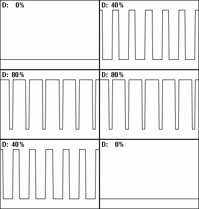
In an Alternating Current Waveform the ratio of "On" time to "Off" time (or positive time to negative time) is known as the Duty Cycle. Changing the Duty Cycle modifies the width of the pulses, and is also called Pulse Width Modulation. We'll be using Pulse Width Modulation (or PWM for short) later on, to control things like motors and dim lights using micro-controllers like the Arduino.

Impedance
Up to this point we have really only talked about Ohm's Law in term of Direct Current circuits, and of course, things get more complicated as you apply Alternating Current to a circuit. Because the circuit can react differently depending on the frequency of the Alternating Current applied, we use the term Impedance to describe it.
In quantitative terms, it is the complex ratio of the voltage to the current in an alternating current (AC) circuit. Impedance extends the concept of resistance to AC circuits, and possesses both magnitude and phase, unlike resistance, which has only magnitude. When a circuit is driven with direct current (DC), there is no distinction between impedance and resistance; the latter can be thought of as impedance with zero phase angle.
It is necessary to introduce the concept of impedance in AC circuits because there are two additional impeding mechanisms to be taken into account besides the normal resistance of DC circuits: the induction of voltages in conductors self-induced by the magnetic fields of currents (inductance), and the electrostatic storage of charge induced by voltages between conductors (capacitance). The impedance caused by these two effects is collectively referred to as reactance and forms the imaginary part of complex impedance whereas resistance forms the real part.
The symbol for impedance is usually Z and it may be represented by writing its magnitude and phase in the form |Z|∠θ. However, cartesian complex number representation is often more powerful for circuit analysis purposes.
Historical
- In the War of Currents Thomas Edison and Nikola Tesla (and their proxies - Westighouse and General Electric) waged commercial war to see if America would have DC (Edison) or AC (Tesla) electricity wired to every home. As you likely know, AC won the war, as DC is more lossy to distribute over long distances. Tesla was an amazing engineer, as he could hold complete, complex designs and simulations in his head before ever putting them down on paper.
