Assembly Guide - PancakeLegend/Simon GitHub Wiki
So you've got a bag full of parts in front of you and want to turn it into something fun? It looks like you're in the right place! Let's guide you through the assembly process. Please read the entire guide before starting.
Assembly time: 30-45 minutes
Assumed knowledge
If you haven't soldered before, don't worry. While it would be helpful if you have some experience, there's no reason why this can't be a great first soldering project.
There's nothing tricky here, so any basic through-hole soldering tutorial will have you covered. Here's a good one.
Safety
Wear protective glasses when soldering and cutting the legs of components. The legs can fly off unexpectedly when you snip them!
Button batteries can be very harmful if swallowed. Keep this device (and its battery) safe from small children and animals.
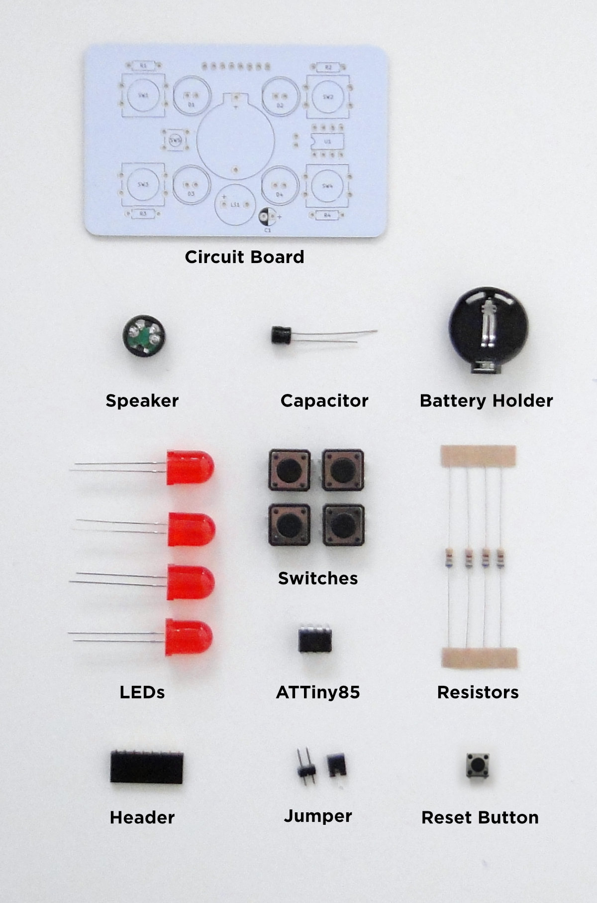
In the kit
Simon v1-1 circuit board (PCB)
Speaker, 10v 100uf Capacitor, CR2032 Battery holder
4x 10mm LEDs, 4x 12mm tactile switches, 4x 680Ω resistors
ATTiny85 microcontroller
8-pin programming header (optional)
Header, Jumper, Reset Button
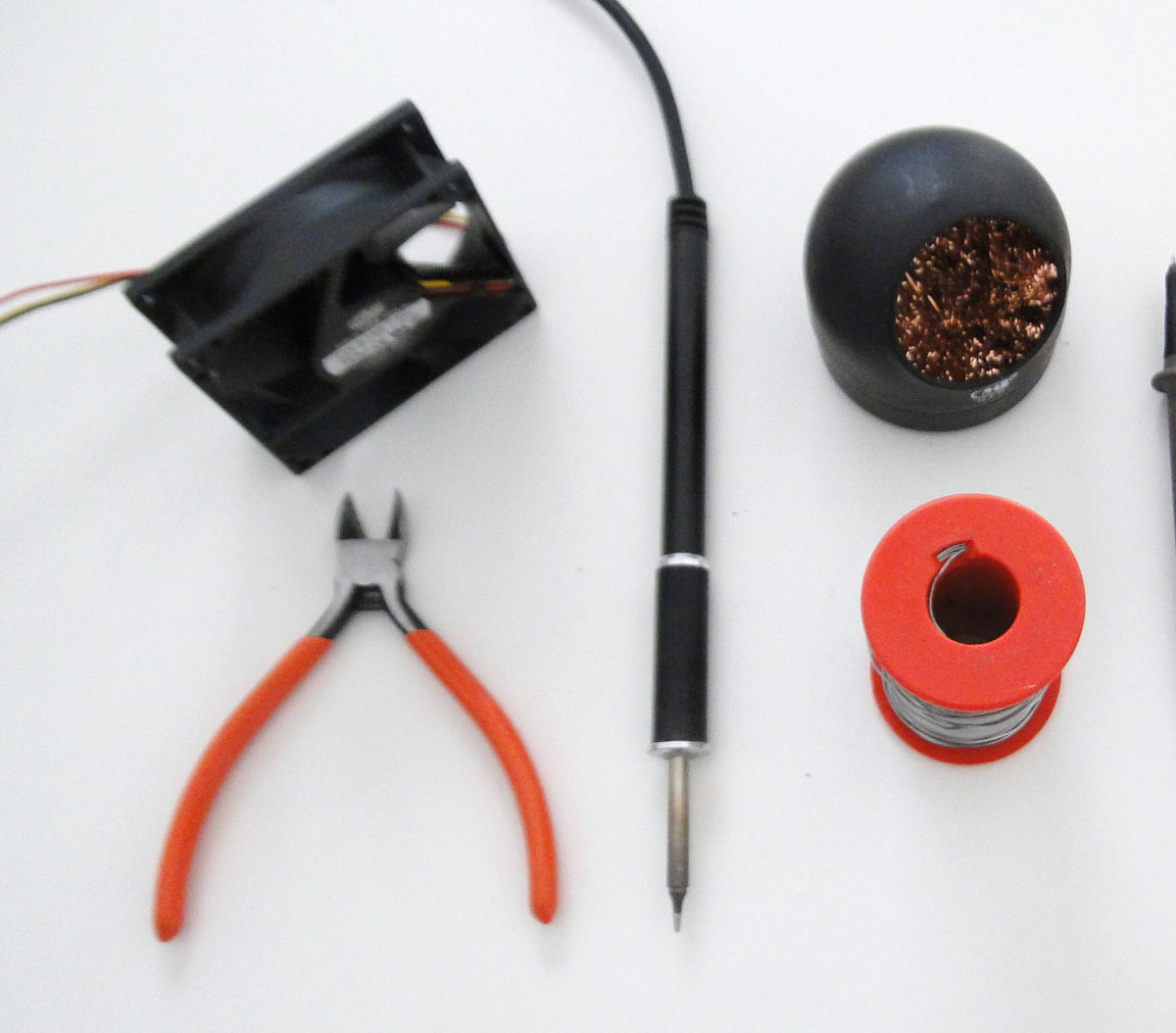
Required tools
Soldering iron
- Solder
- Wet sponge / brass wool
- Safety glasses
- Exhaust fan
A workbench or something to protect your table (a wooden chopping block is fine).
Side cutters
Let's get started!
Resistors
Bend the legs of the resistors and insert them into the holes for R1 - R4
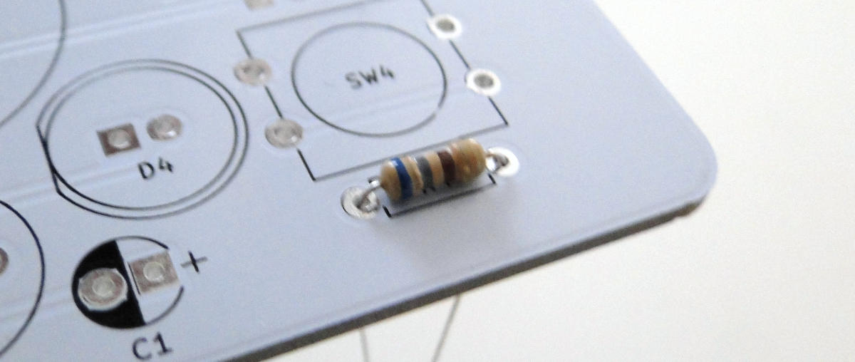
After inserting all the resistors, flip the board over and solder the legs. Cut off the legs with your side cutters after soldering.
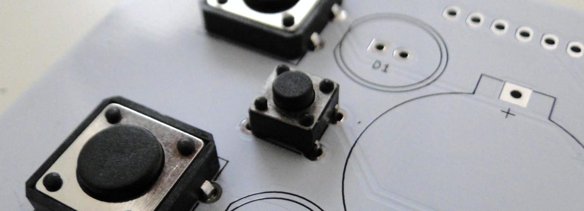
Tactile switches
Before inserting the switches, check that the legs aren't unevenly bent. Locate the tips of the pins in the holes before pushing the switch all the way in, this may require a little force.
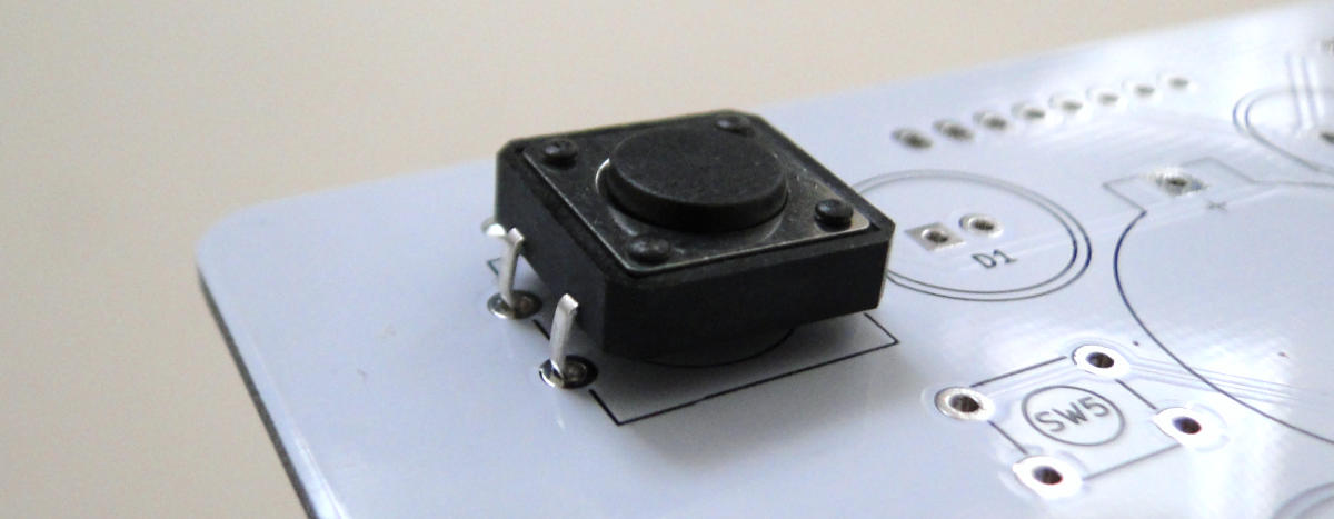
Make sure that all of the legs protrude through to the other side before soldering.
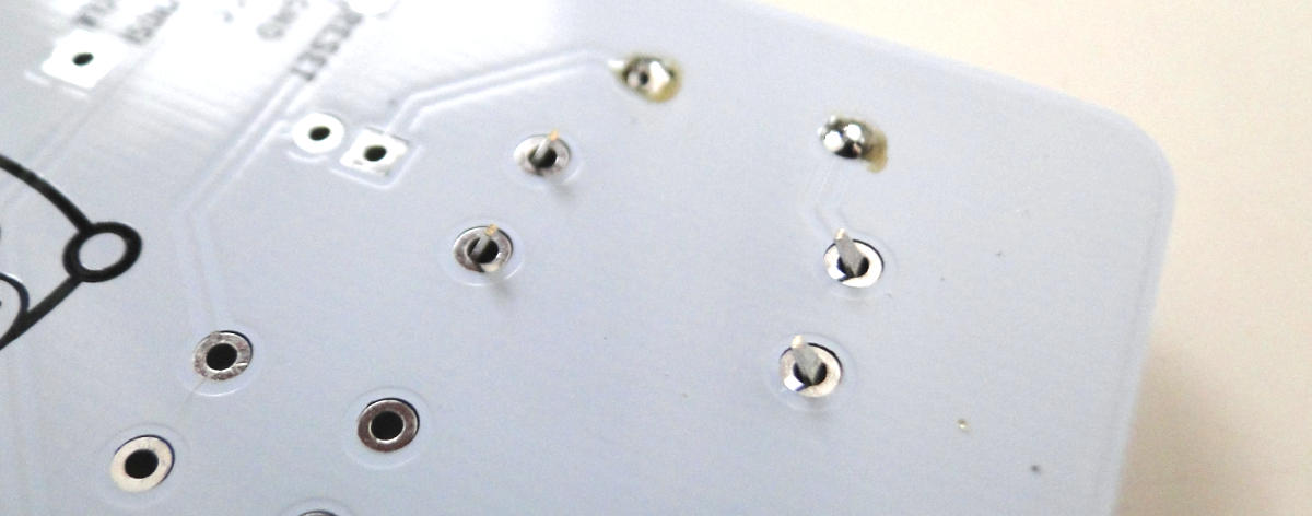
Solder all of the solder points for all of the 4 large switches.
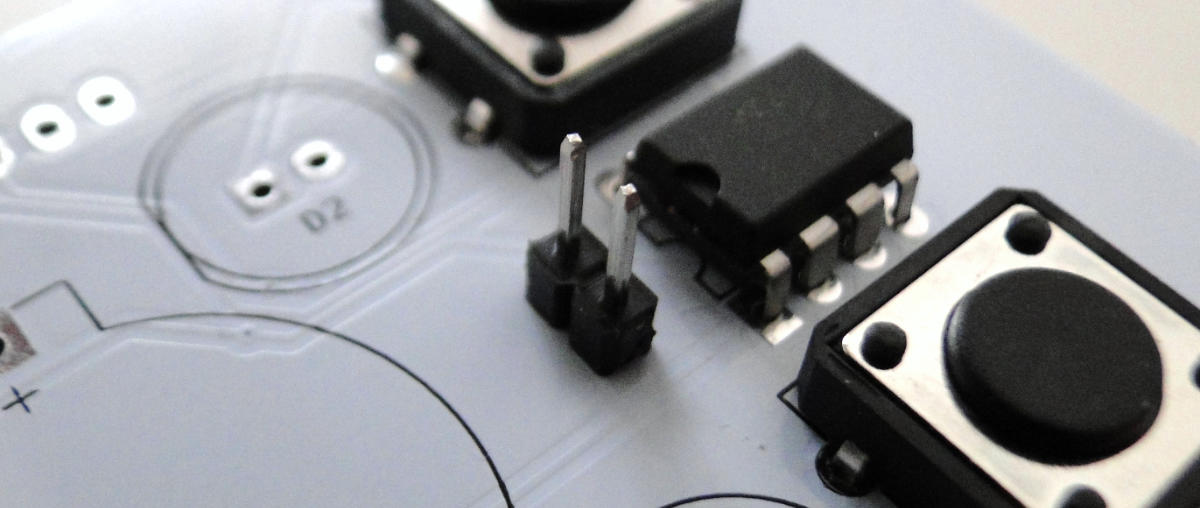
ATTiny85
Check the pins are straight before inserting the ATTiny85. Make sure that the locating notch is on the same side as the notch on the footprint. Update: The new batch of ATTiny85s has a reference dot instead of the notch. The dot should be on the same side as the notch as shown in the picture. Don't be concerned that it looks a little different.

Solder all 8 pins of the ATTiny85 from the other side.

Reset Button
Insert and then solder the reset button in the same way as the tactile switches.
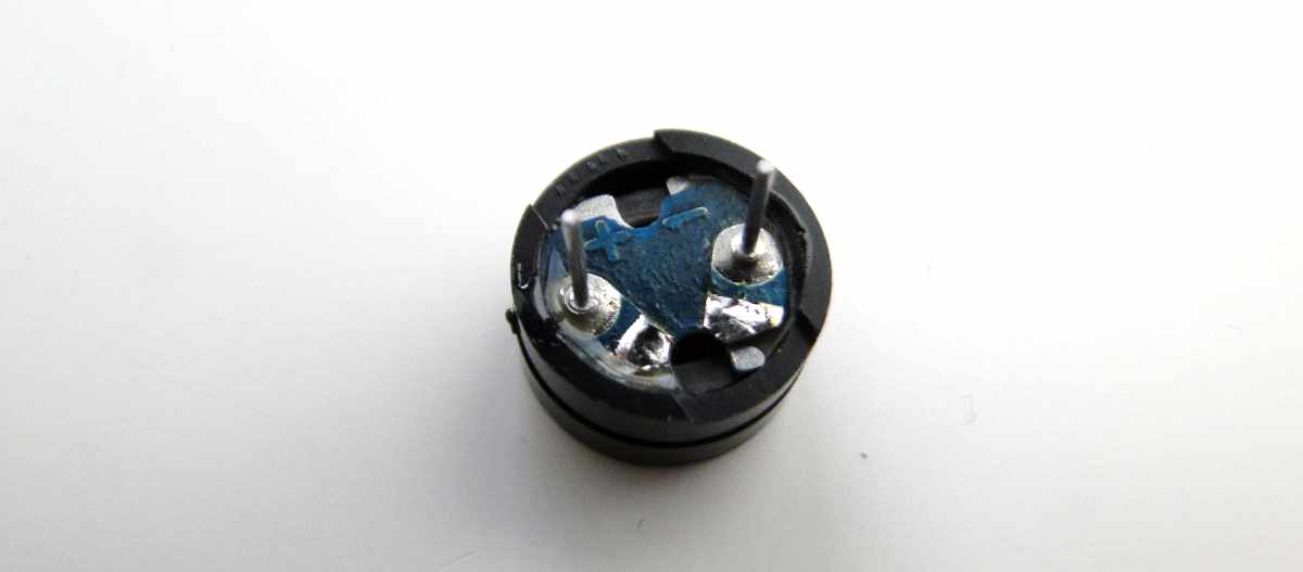
Speaker
LS1 - Make sure the + on the plastic case and on the bottom of the speaker aligns with the + on the board.

Capacitor
C1 is an aluminium electrolytic capacitor. This component has a polarity, it is important that this component is inserted the right way around. One of its legs will be longer than the other one, this is the anode (+). Make sure that you insert the capacitor in the correct orientation.

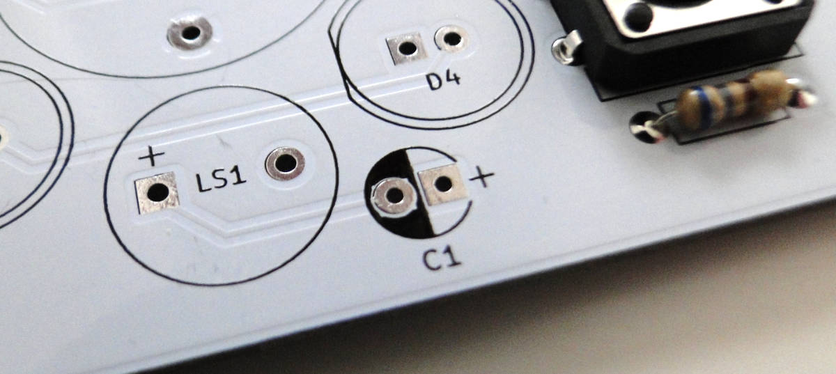
Solder the capacitor in place then cut the legs with the side cutters.
LEDs
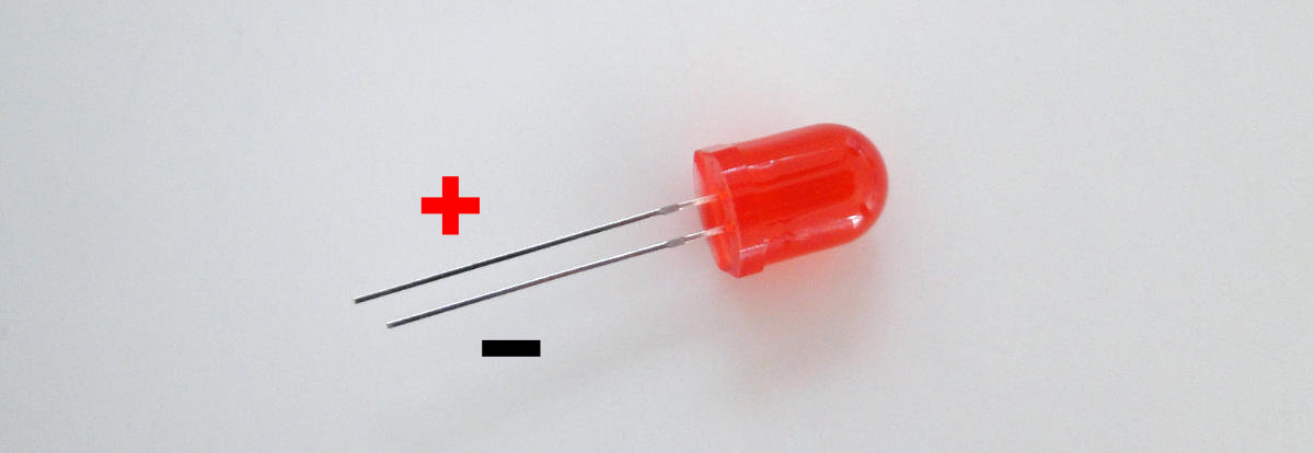
The LEDs also have a polarity. It's important to make sure that the short leg goes into the hole with the square pad when inserting these components.
Solder then trim the legs.
Battery Holder
Use the outline of the footprint to orientate the battery holder correctly. The legs can get a bit bent in transit, you may need to straighten them so they fit into the holes.

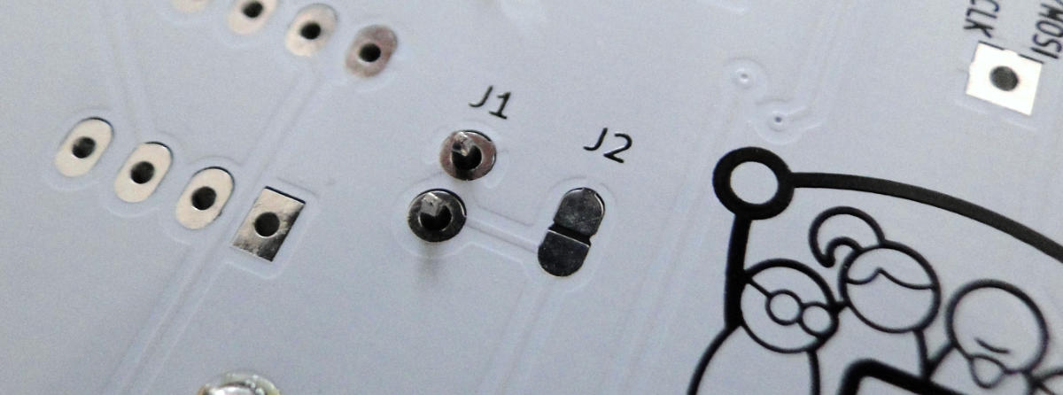
Jumper
The jumper pins are an optional component, or rather they represent a choice. If you never plan on reprogramming the ATTiny85, instead of including the jumper pins, you can bridge the pads of J2 with a blob of solder. The reason for this jumper is that LEDs 3 and 4 are connected to pins of the ATTiny85 that are required for reprogramming. The J1 jumper gives you a way to disconnect them during the reprogramming process, the J2 solder bridge alternatively permanently connects that part of the circuit.
Don't solder both pins at once. Keeping the pins upright when soldering can be tricky. You can use some blu-tak to keep them in place. After soldering the first pin, check that the jumper header is straight and upright, if not, you can re-wet the solder and straighten the pins - then solder the other.
If you choose to include the jumper pins, put the jumper connector on the pins after soldering.
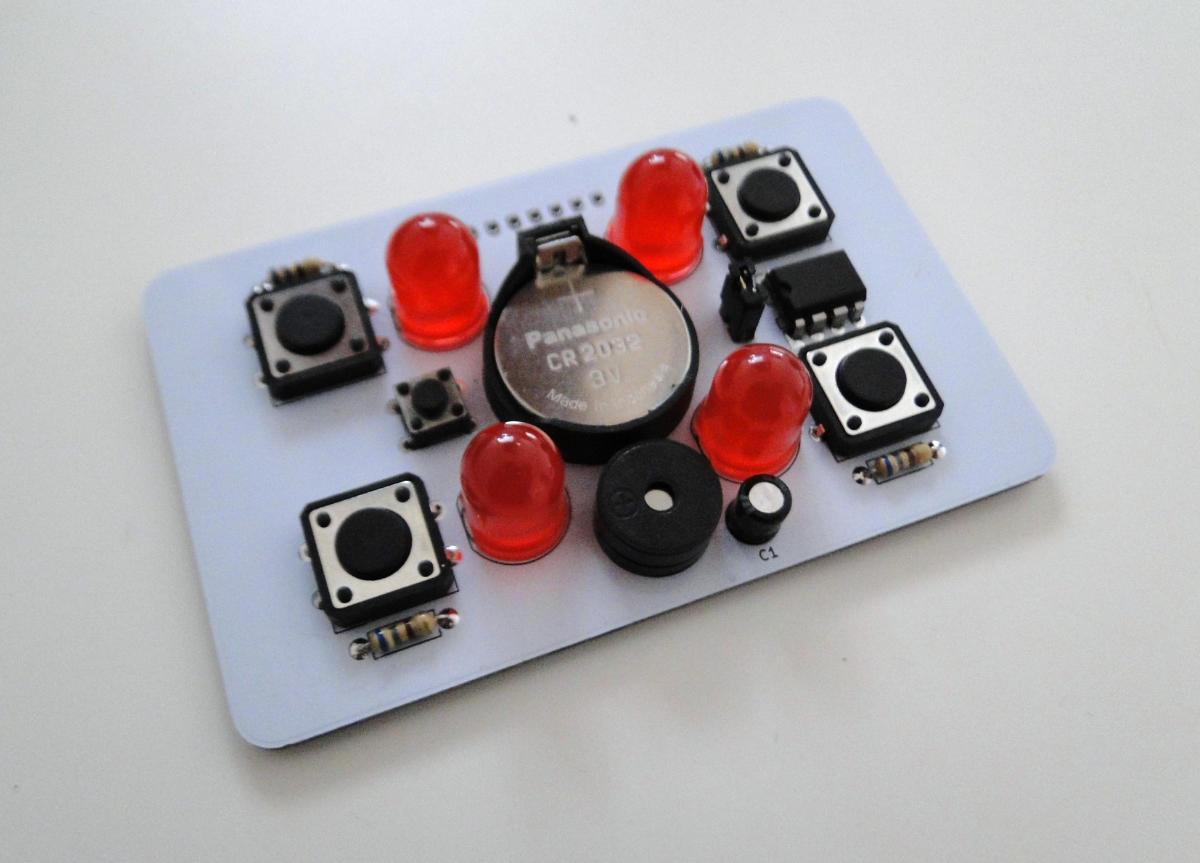
Congratulations!
You've completed the build! Insert a CR2032 battery and press the reset button to start the game. Play!