Firewall and Zones Set Up - Paiet/Capstone GitHub Wiki
- Went to https://192.168.204.129/
Create a New Security Zone
-
"Security zones are a logical way to group physical and virtual interfaces on the firewall to control and log the traffic that traverses your network through the firewall. An interface on the firewall must be assigned to a security zone before the interface can process traffic. A zone can have multiple interfaces of the same type (for example, Tap, Layer 2, or Layer 3 interfaces) assigned to it, but an interface can belong to only one zone."
-
In the web interface, select Network > Zones.
-
Click Add to create a new zone.
-
Configure the following:
| Parameter | Value |
|---|---|
| Name | outside |
| Type | Layer3 |
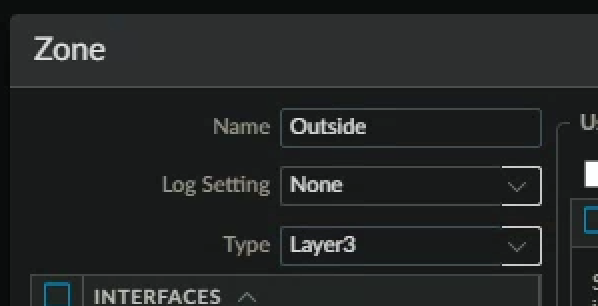
- Click ok
Create Interface Management Profiles
- "An Interface Management Profile protects the firewall from unauthorized access by defining the services and IP addresses that a firewall interface permits. You can assign an Interface Management Profile to Layer 3 Ethernet interfaces (including subinterfaces) and to logical interfaces (aggregate, VLAN, loopback, and tunnel interfaces)."
- In the web interface, select Network > Network Profiles > Interface Mgmt.
- Click Add to create an Interface Management Profile.
- The Interface Management Profile configuration window should appear.
- Configure the following:
| Parameter | Value |
|---|---|
| Name | ping-and-response-pages |
| Network Services | Select Ping and Response Pages check boxes |
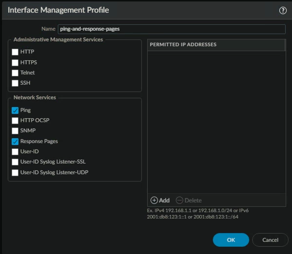
- Click ok
- Click Add to create an Interface Management Profile.
- Configure the following:
| Parameter | Value |
|---|---|
| Name | ping-only |
| Network Services | Select Ping check box |
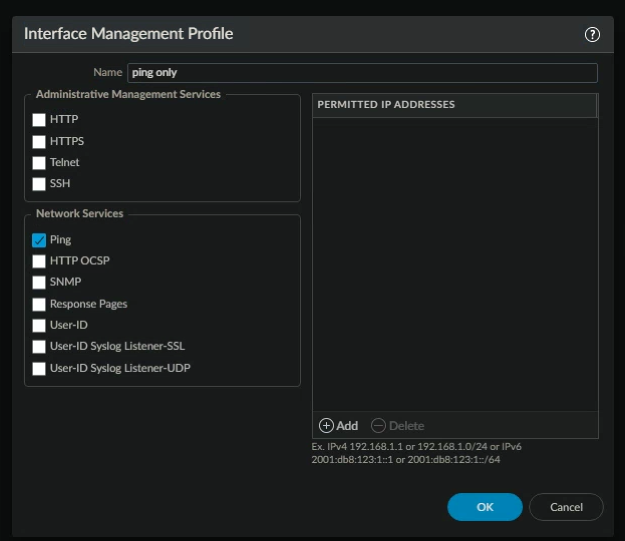
- Click ok
- Verify that your configuration is like the following

Configure Ethernet Interfaces
- "Firewall interfaces, or ports, enable a firewall to connect with other network devices and other interfaces within the firewall. The interface configuration of the firewall ports enables traffic to enter and exit the firewall. You can configure the firewall interfaces for virtual wire, Layer 2, Layer 3, and tap mode deployments."
- In the web interface, select Network > Interfaces > Ethernet.
- Click ethernet1/2 to configure the interface
- Configure the following:
| Parameter | Value |
|---|---|
| Comment | inside interface (LAN) |
| Interface Type | Layer3 |
| Virtual Router | None |
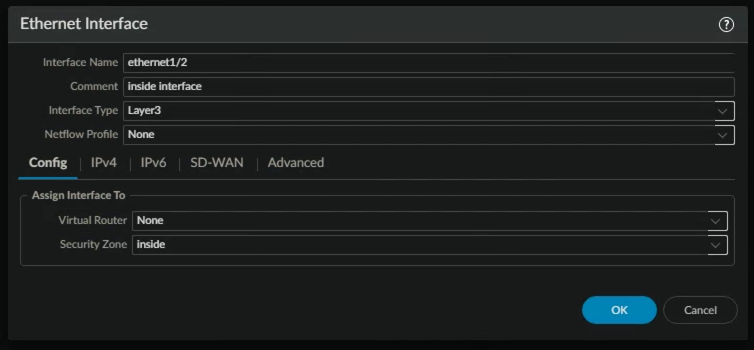
- Click the Security Zone drop-down list and select New Zone: (It will say Inside after you finish configuring the zone)
| Parameter | Value |
|---|---|
| Name | inside |
| Type | Layer3 |
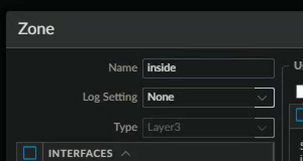
- Click ok
- You will be taken back to the ethernet interface set up page.
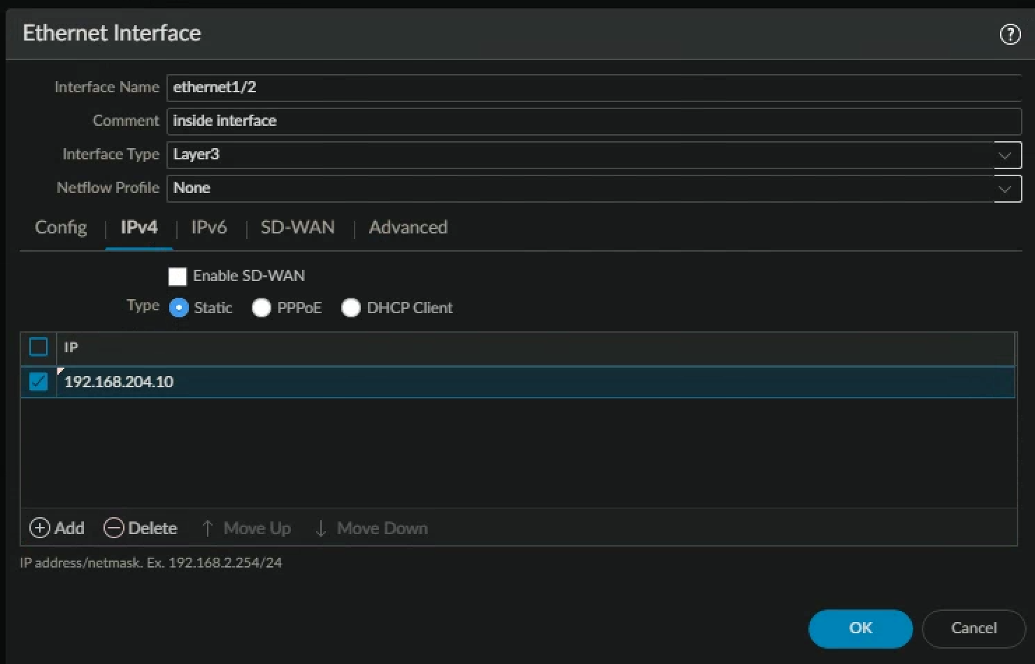
- Click the Ethernet Interface IPv4 tab (don't forget CIDR Notation)
| Parameter | Value |
|---|---|
| Type | Verify that the Static radio button is selected |
| IP | Click Add and type 192.168.204.10/24 |
- Click the advanced tab
- Click the Management Profile drop-down list and select ping-and-response-pages
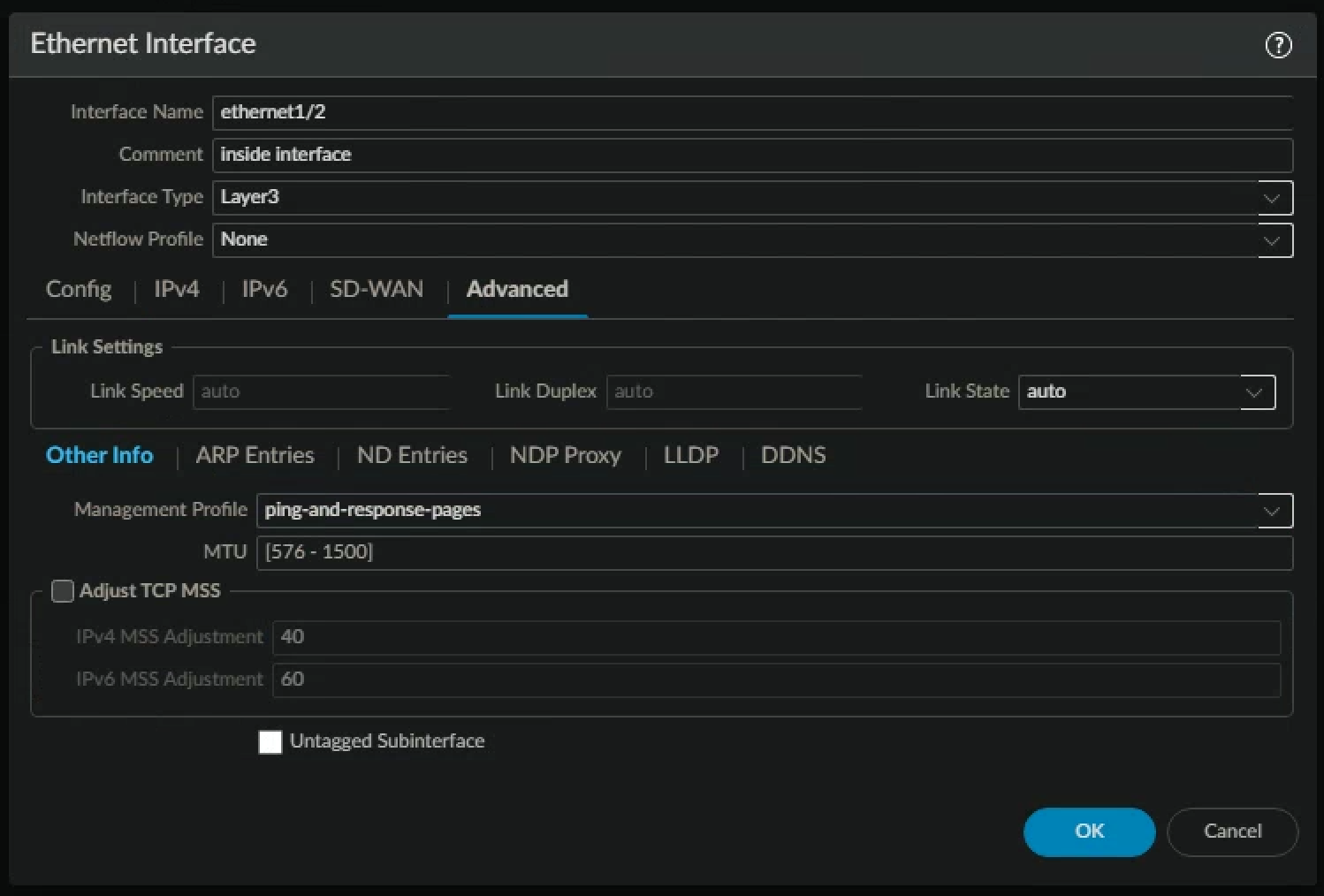
- Click OK to close the Ethernet Interface configuration window
- Click ethernet1/3 to configure the interface
- Configure the following
| Parameter | Value |
|---|---|
| Comment | dmz interface |
| Interface Type | Layer3 |
| Virtual Router | None |
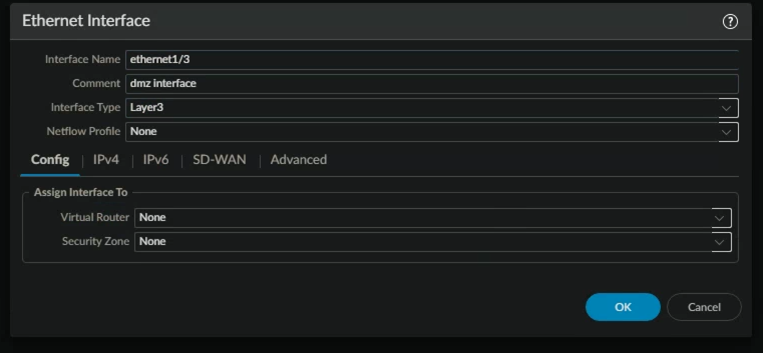
- Click the Security Zone drop-down list and select New Zone
- Configure the following
| Parameter | Value |
|---|---|
| Name | dmz |
| Type | Layer3 |
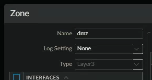
- Click OK to close the Zone configuration window
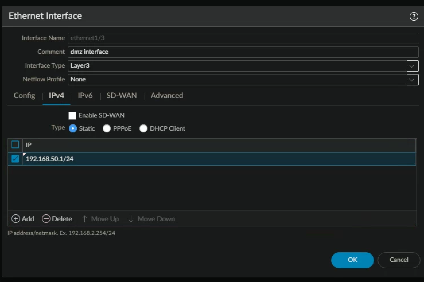
- Click the IPv4 tab.
- Configure the following
| Parameter | Value |
|---|---|
| Type | Static |
| IP | Click Add and type 192.168.50.1/24 |
- Click the Advanced tab.
- Click the Management Profile drop-down list and select ping-only.
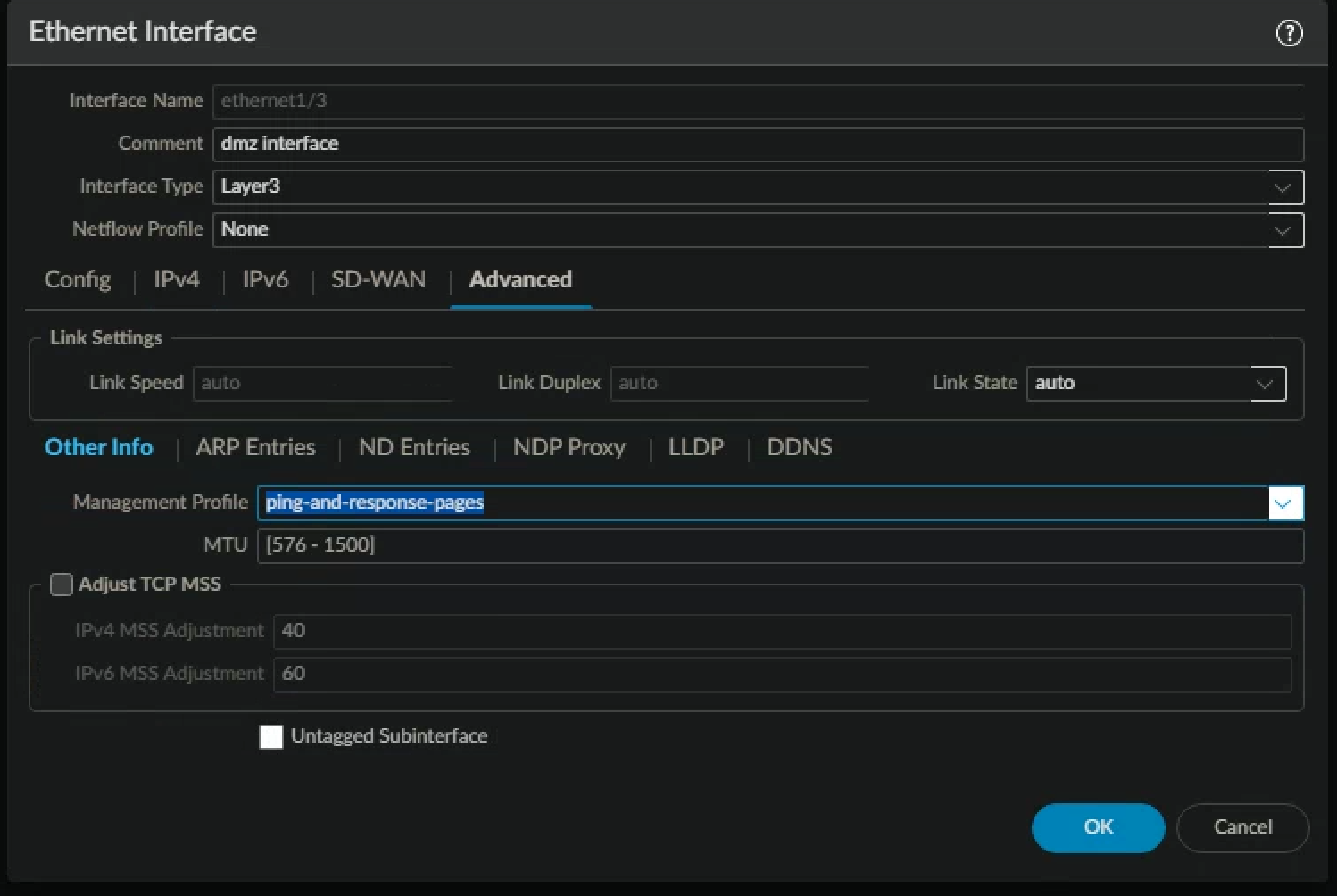
- Click OK to close the Ethernet Interface configuration window.
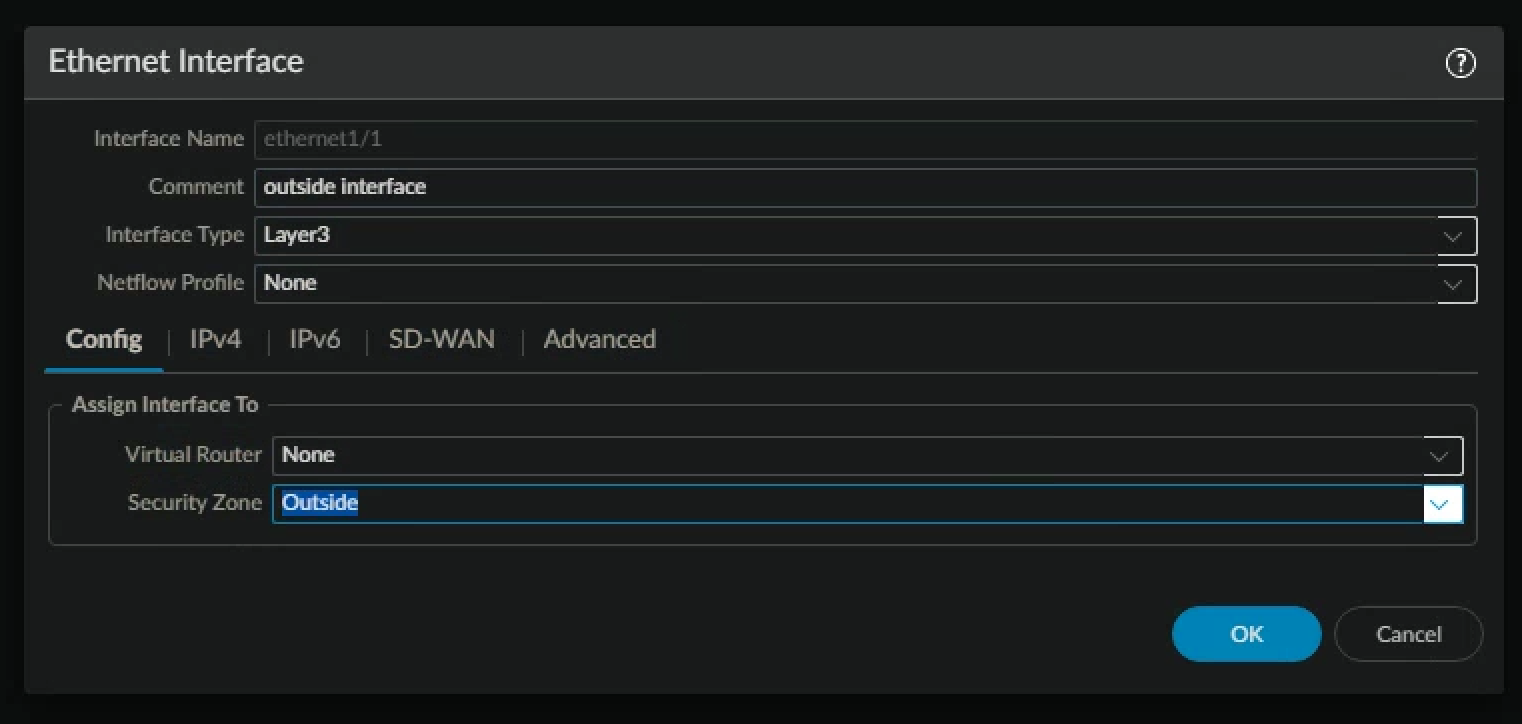
- Click ethernet1/1 to configure the interface.
- Configure the following
| Parameter | Value |
|---|---|
| Comment | outside interface (WAN) |
| Interface Type | Layer3 |
| Virtual Router | None |
| Security Zone | outside |
- Click the IPv4 tab and configure the following
| Parameter | Value |
|---|---|
| Type | DHCP Client |
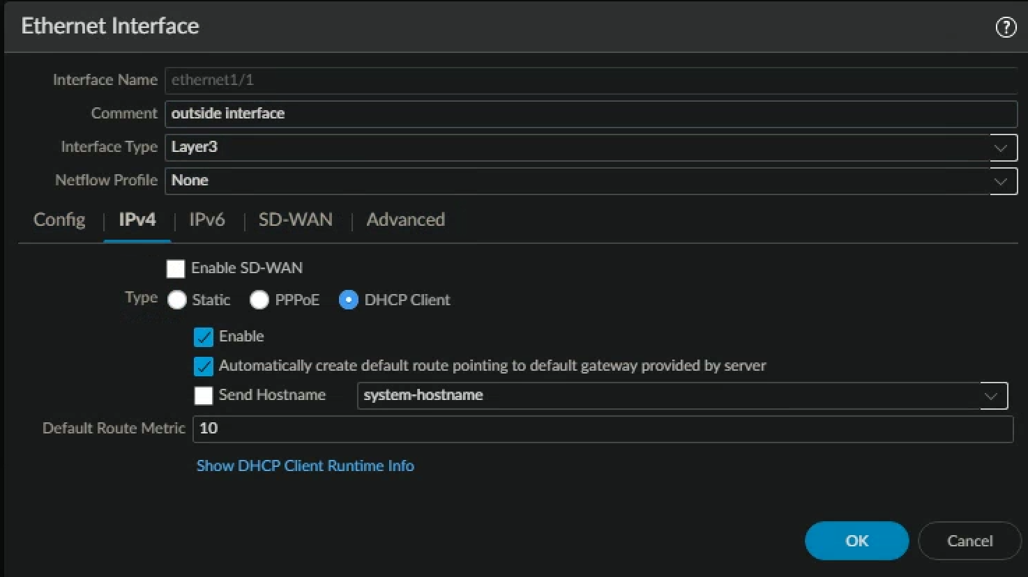
- Click OK to close the Ethernet Interface configuration window.
- Click ethernet1/4 to configure the interface
- Configure the following
| Parameter | Value |
|---|---|
| Comment | vWire zone named danger |
| Interface Type | Virtual Wire |
| Virtual Wire | None |
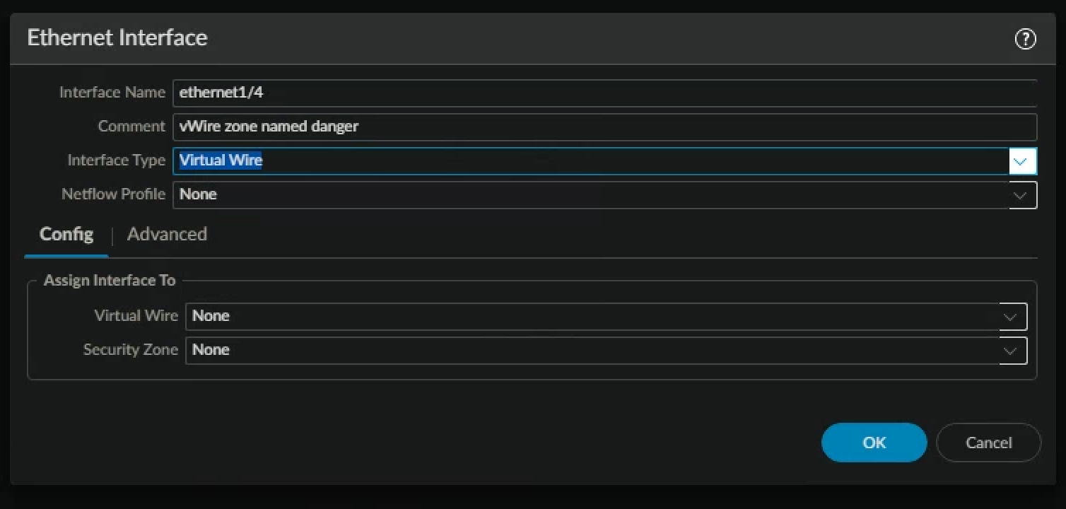
- Click the Security Zone drop-down list and select New Zone.
- Configure the following
| Parameter | Value |
|---|---|
| Name | danger |
| Type | Virtual Wire |
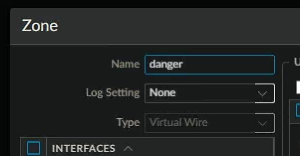
- Click OK to close the Zone configuration window
- Click OK to close the Ethernet Interface configuration window.
- Click ethernet1/5 to open the interface.
- Configure the following
| Parameter | Value |
|---|---|
| Comment | vWire zone named danger |
| Interface Type | Virtual Wire |
| Virtual Wire | None |
| Security Zone | danger |
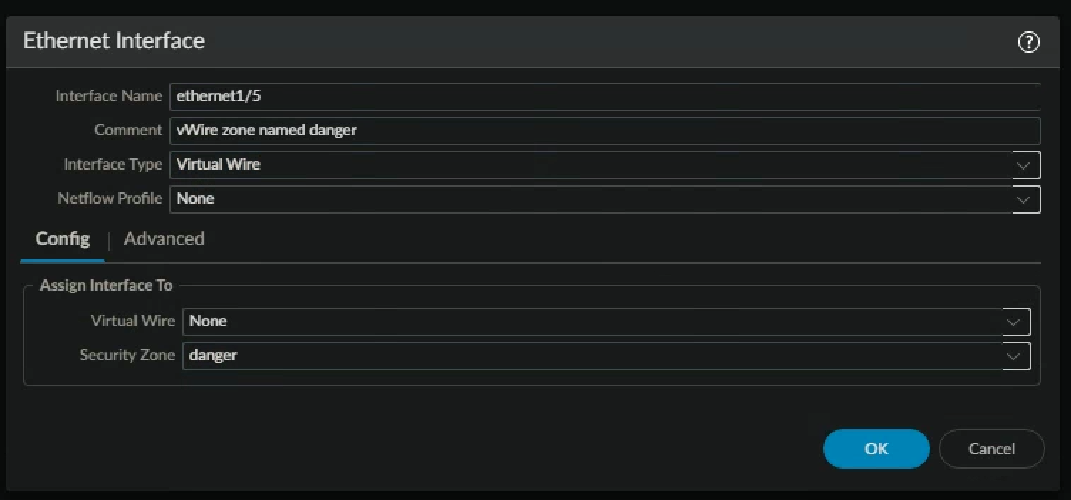
- Click OK to close the Ethernet Interface configuration window.
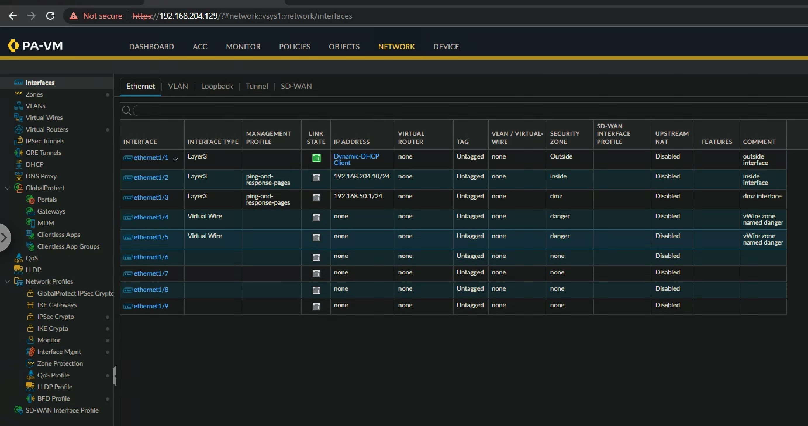
- Verify that your configuration is like the following
Create a Virtual Wire
- "A virtual wire interface binds two Ethernet ports. A virtual wire interface allows all traffic or just selected VLAN traffic to pass between the ports. No other switching or routing services are available."
- In the web interface, select Network > Virtual Wires.
- Click Add
- Configure the following
| Parameter | Value |
|---|---|
| Name | danger |
| Interface 1 | ethernet1/4 |
| Interface 2 | ethernet1/5 |
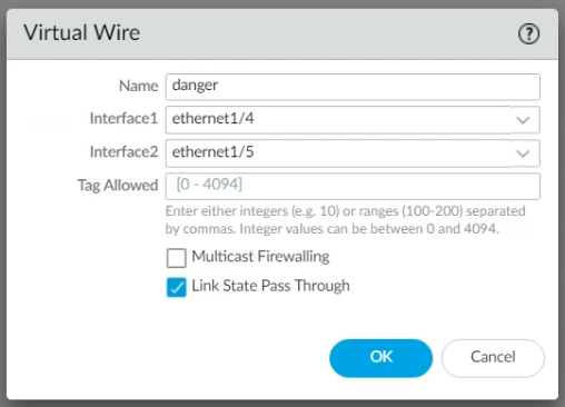
- Click OK to create your virtual wire
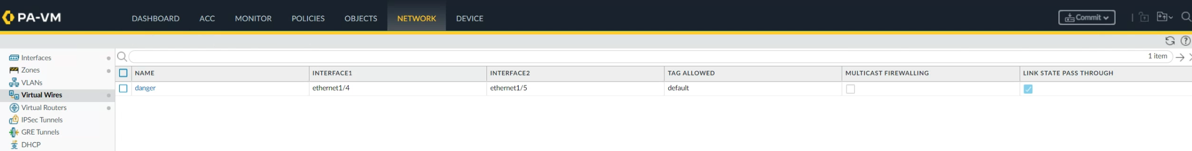
- Verify that your configuration is like the following
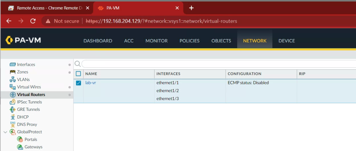
Create a Virtual Router
- In the web interface, select Network > Virtual Routers.
- Click default to open the default virtual router.
- Rename the default router lab-vr.
- Locate the General tab > Interfaces box and click Add.
- Add the following interfaces: ethernet1/1, ethernet1/2, and ethernet1/3
- Click OK to close the Virtual Router - default window.
- Commit all changes
Modify Outside Interface Configuration
- "In this section, you will reconfigure Ethernet Interface 1/1 to use a static IP address and add a static route to your virtual router. Under most conditions you will configure the firewall’s Layer 3 interfaces with static IP addresses. We initially configured ethernet1/1 to use the DHCP client function only to illustrate the feature should you ever need it."
- In the web interface, select Network > Interfaces > Ethernet.
- Select but do not open ethernet1/1:
- Click Delete, then click Yes.
- Commit all changes.
- Click ethernet1/1 to configure the interface.
| Parameter | Value |
|---|---|
| Comment | outside interface (WAN) |
| Interface Type | Layer3 |
| Virtual Router | lab-vr |
| Security Zone | outside |
- Click the IPv4 tab and configure the following:
| Parameter | Value |
|---|---|
| Type | Static |
| IP | Click Add and type 192.168.204.10/24 |
- Click OK to close the Ethernet Interface configuration window.
- In the web interface, select Network > Virtual Routers.
- Click the lab-vr virtual router to open.
- Click the Static Routes vertical tab:
- Click Add and configure the following static route
| Parameter | Value |
|---|---|
| Name | default-route |
| Interface | ethernet1/1 |
| Destination | 0.0.0.0/0 |
| Next Hop | Verify that IP Address is selected |
| Next Hop IP Address | 192.168.204.2/24 |
- Click OK to add the static route.
- Click OK to close the Virtual Router – lab-vr configuration window.
- Commit all changes.