Hardware build log - OxRAMSociety/RobotArm GitHub Wiki
- Connect the power supply.
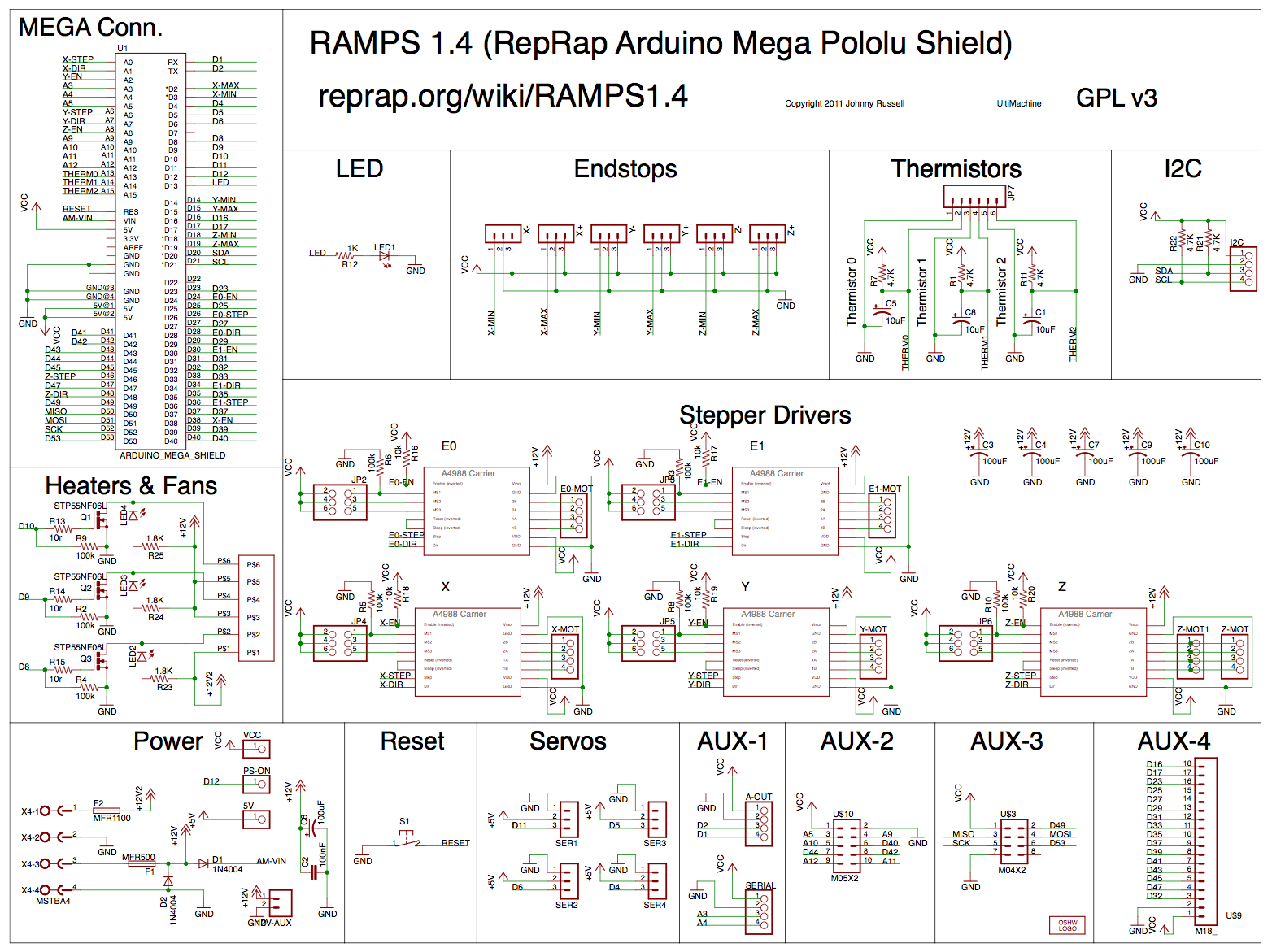
- Connect the RAMPS 1.4 board matching the colors of the cables.
- Setup the jumpers and install the 5 drivers on the RAMPS 1.4. Since we are using A4988 drivers, setting all the jumpers will set the micro stepping to 1/16 of a step.
- Connect the motors.
- Connect the stepper motor extender directly to the power supply matching the colors of the cables and install the driver.
- Connect the extender to the main RAMPS board.
We need 5 cables: 2 for 5V and ground (here red and black respectively) and 3 for the enable (yellow), step (orange), and direction (green) pins of the motor.
Here we are using some pins in the AUX-2 cluster, which provides 5V and ground pins as well as the unused pins D40 (green, direction), D42 (orange, step) and D44 (yellow, enable).
- The extender can be configured with a DIP switch instead of jumpers. In this case we are using a DRV8825 driver, so we set the last switch to enable 1/16 micro stepping.
- Connect the 6th motor to the extender.
- Connect the LCD display smart controller to the RAMPS 1.4 board
missing image