Arduino and RAMPS - OxRAMSociety/RobotArm GitHub Wiki
RAMPS 1.4 is an Arduino MEGA 2560 shield commonly used for 3D printers. It supports 5 stepper motors, endstops, multiple fans, a heated bed and a monitor.
It operates at 12V, and has two pairs of connectors for power (one at 11A and one at 5A). We won't need the former, since this is only powering the heated bed.
The schematics for the board is the following.
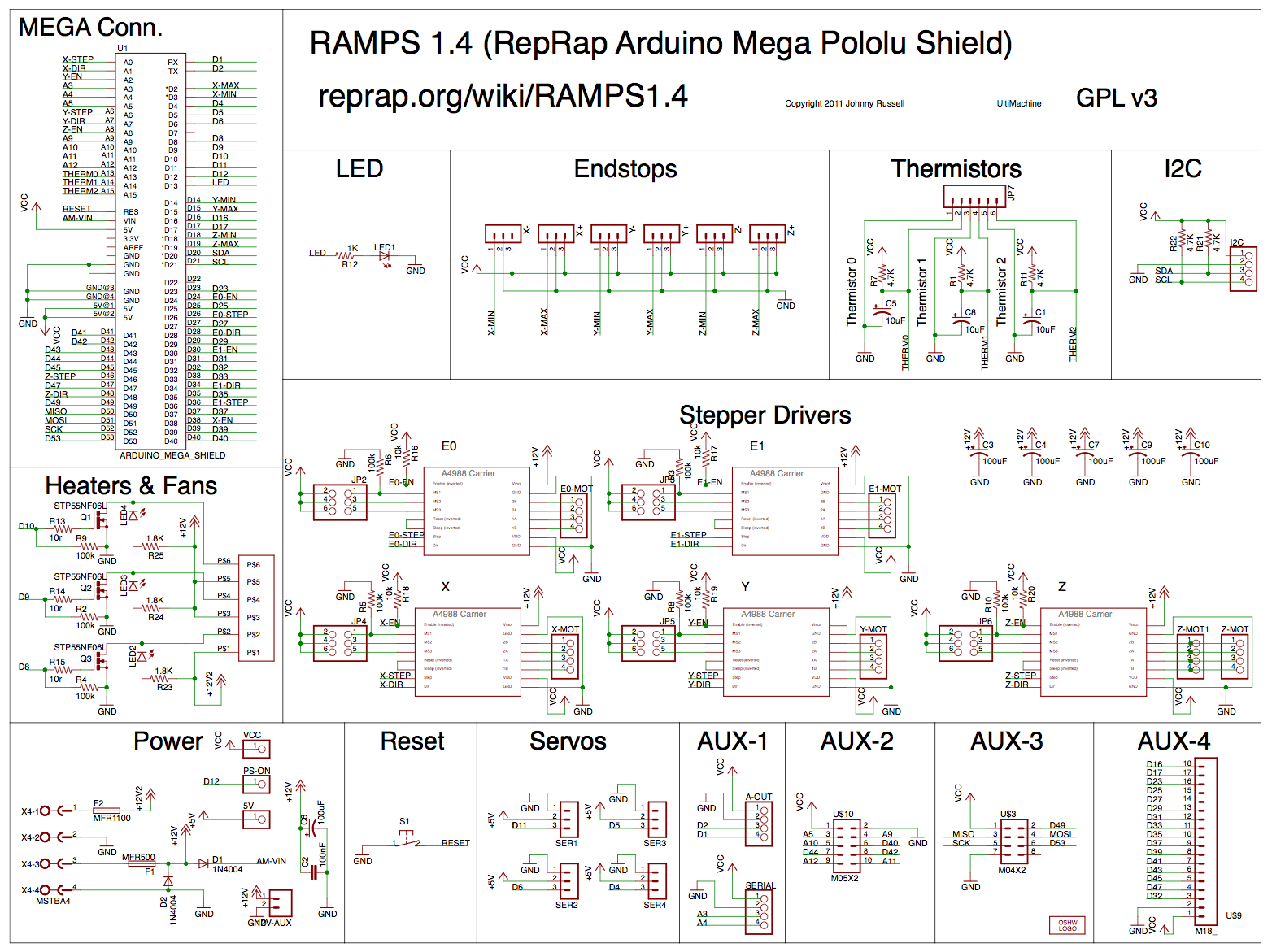
To control the stepper motors, some of the analog pins are used as digital.
As such most examples will use the "digital notation" (e.g., 56 instead of A2) and in general any pin number higher than 53 corresponds to analog pin A(54-pin).
A snippet of code with all pins defined can be found here.
We don't really need endstops for the robot arm, but let's keep in mind that we have access to them (for example as safety stop?).
The most common type of mechanical endstops is the Normally Closed and show a LOW read when triggered.
Depending on the type of endstop you might want to use Arduino's internal pull-up resistors by setting pin mode to INPUT_PULLUP.
Something like this should work
#define ENDSTOP_X_MIN 3

setup() {
    // ...
    pinMode(ENDSTOP_X_MIN, INPUT)
    // ...
}

loop() {
    // ...
    if (digitalRead(ENDSTOP_X_MIN) == LOW) {
        // do stuff when endstop is triggered
    }
    // ...
}
We will be able to controll 5 out of 6 stepper motors from the RAMPS 1.4. For other ways to extend the board see the following section.
See the drivers section in the RepRap page for driver compatibility information.
Before connecting the driver, you should set up the jumpers to define the microsteps for each particular driver. Experiment with this to see what works best for our setup.
The trimpod on the drivers can be used to limit the maximum current provided to the stepper motor. If the stepper motor gets hot easily, consider turning down (counter clockwise) the max current.
We need different NEMA motors for the arm, but the this shouldn't make any huge difference in the connections with the board.
Motor connectors can be straight or crossed (check for continuity to figure out what you have, if necessary).
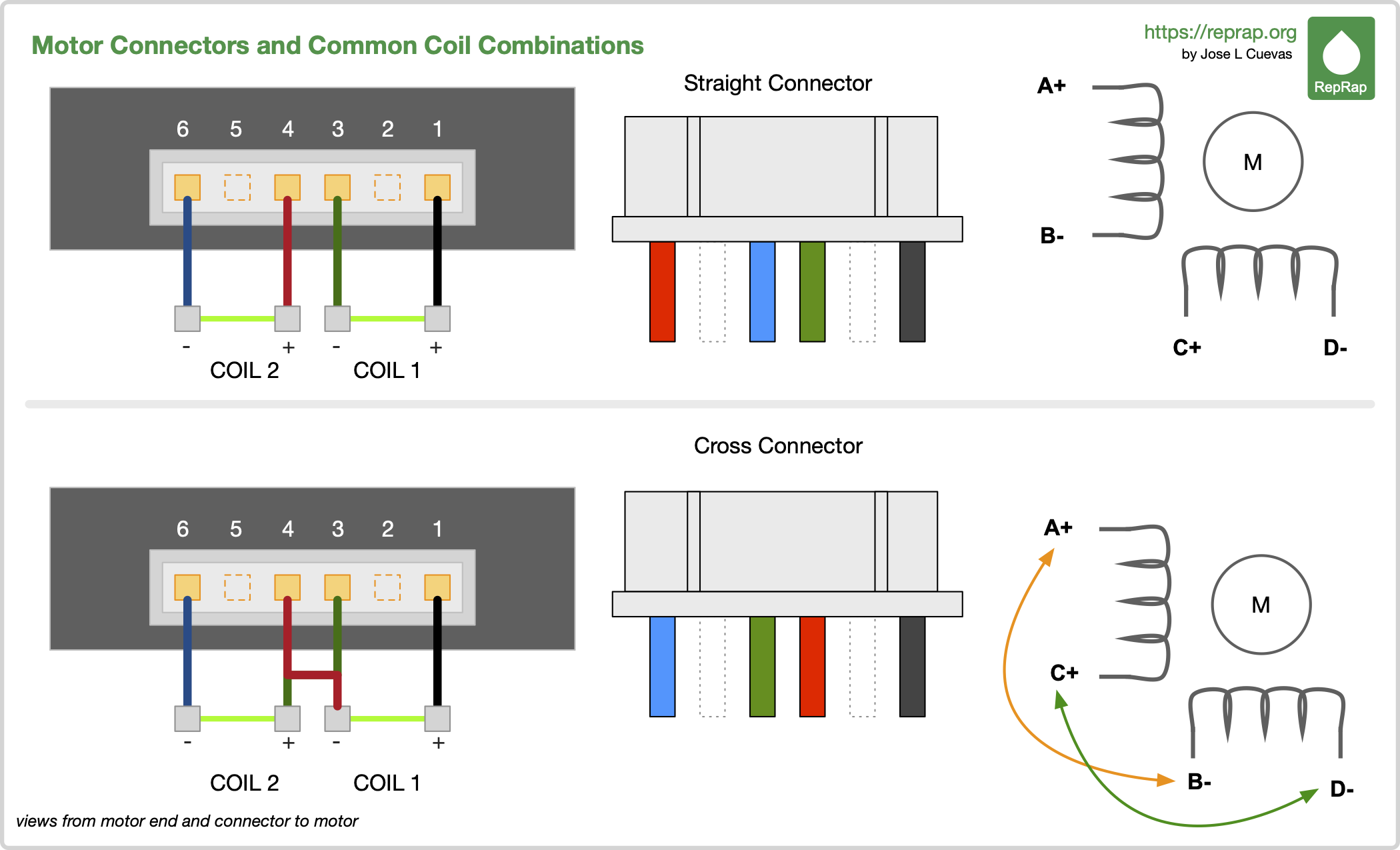
The connection goes in only one way on the motor side. On the board side, as far as I can tell, connecting the cable in one way or another will only affect the direction of rotation.
We only need to connect the pair of cables marked as 5A to a power supply able to sustain 12V (and provide at least 5A of current).
Note: a power supply that provide more amperage (e.g., 30A) is fine, while we shouldn't run more than 12V through the system (the RAMPS is able to handle 24V but the Arduino Mega is not).
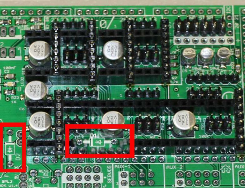
The Arduino MEGA is powered through the RAMPS board if the D1 diode is present, otherwise you will need to power it separately (allowing for more voltage to be supplied to the RAMPS shield).
You can find many videos on YouTube on how to setup a power supply. Here is one good example.
You will need some cables (e.g., the cables to connect a laptop charger to the AC socket) and a screwdriver to finetune the output voltage.
Remember to adjuct the voltage provided by the power supply before connecting it to the system.
In order to connect a 6th stepper motor to the RAMPS 1.4 we use a generic stepper motor extender like the one shown in the picture below. For different ways of extending the RAMPS board with additional stepper motors see this.

The stepper motor extender needs to be connected to the 12V power supply and will connect the stepper motor to the RAMPS 1.4.
To connect the extender to the RAMPS, we need to connect 5V and ground pins along with enable, direction, and step pins.
In our case we are using the AUX-2 cluster in the RAMPS board which provides multiple 5V and ground pins along with D40, D42 and D44 unused pins (see [build log] for more details).
We can then setup the additional motor in the Arduino code like this:
#define A_STEP_PIN         42
#define A_DIR_PIN          40
#define A_ENABLE_PIN       44
In this particular extension board, the microsteps for the motor driver can be configured with a DIP switch (instead of the jumpers used in the RAMPS board).
The RAMPS 1.4 board is compatible with a standard 128x64 LCD display. RAMPS kits for DIY 3D printers usually provide a graphic smart controller similar to the one shown below.

The LCD supports a 4bit serial display interface and is compatible with the u8g2 Arduino library.
According to the pinout
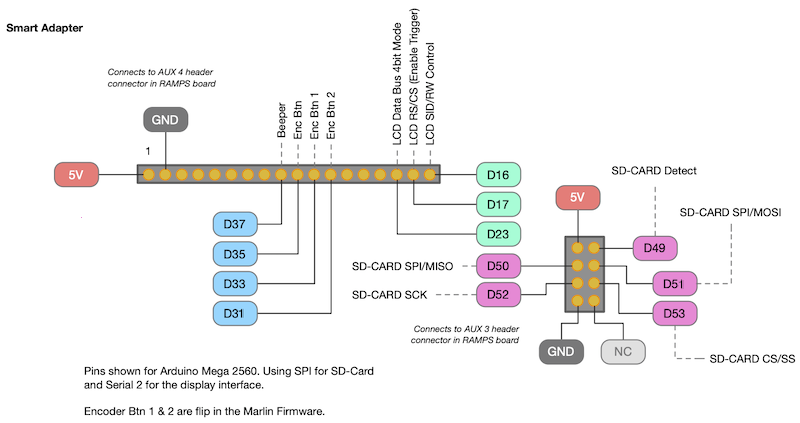
the LCD display can be initialised as follows:
#include <SPI.h>
#include <U8g2lib.h>

// ...

#define LCD_CS 16
#define LCD_MOSI 17
#define LCD_SCK 23

// ...

U8G2_ST7920_128X64_1_SW_SPI u8g2(U8G2_R0, LCD_SCK, LCD_MOSI, LCD_CS);
Have a look at the example setup code and at the wiki for more information on how to use the LCD display.
You can find some tips on how to troubleshoot the RAMPS shield here.
Unless otherwise stated, the content of this wiki is licensed under
