TSZD2 Hardware Information - OpenSourceEBike/TSDZ2_wiki GitHub Wiki
This project came from Flexible Opensource Firmware.
Most of the reverse engineering information is there, especially Hardware information and manuals
Hurzhurz information (look in the .md files)
[toc] TOC ???How to have list of headers in markdown??? {:toc}
Offical Tongsheng Protocol and reputedly better Hurzhurz version
Connectors
TSDZ2 connectors are Higo HG-F.S-Z*09A, Mini-A. KT-LCD3 uses Higo MiniB
Motor
We know there are 2 type of motors: 36V 4000 RPMs and 48V 4000 RPMs (this later works at 52V also, is the same motor). As for the controller, is just the same for all different configurations: supports from battery 20V up to 60V. Yes, you can run 52v/14s on EITHER motor actually, the '36v type' motor will just spin a little faster with less torque than the '48v type' motor - but they both are compatible.
Winding Resistance
This should be a useful diagnostic, and tell us if TS changes the motors. See. R ,L is measured between any pair of wires (so is 2 windings in series)
| V | R-Measured | R Single | L Single | Measured?? |
|---|---|---|---|---|
| 36 | 0.123 | 0.06 | 76uH | R measured (sb23Nov18), L estimated 76=135*(36/48)^2, Lmeasured 85uH |
| 48 | 0.25 | 0.125 | 135uH |
Gears
| Gear | Teeth | Ratio | rpm@60rpm | Tooth Whine Hz@60rpm |
|---|---|---|---|---|
| Final Gear | 92 | 1 | 60 | 92 |
| Blue Shaft | 10 | 9.2 | 92 | |
| Blue Gear | 36 | 9.2 | 552 | 331 |
| Motor Shaft | 8 | 41.4 | 2484 | 331 |
| Motor Poles | 8 | 331 | - | 331 |
(One way to diagnose gear noise problems can be by spectrum analysis of the whine - you can get an audio analyser for phone.)
Spragg clutch is HF1216 bearing and it has a maximum torque of 12.2 Nm
Motor Controller
see I am a little confused re battery voltage on the standard units, my 48V unit will not run on anything over 56.6v where as a 14s battery fully charged is 58.6v, are you saying that its the controller which is limiting the upper voltage and that we should be able to reprogramme it to suit ? Yes. The hardware supports that range of voltages I wrote before but original firmware is limiting.
CPU Pin Assignment, STM8S105C4 Documents
Similar Kunteng Controller Schematic
- Although uses the STM8S105C4 (should have 16kbytes flash memory) and the original firmware seems to use about 15kbytes of flash memory, I was able to flash a 18Kbytes flash memory (our OpenSource firmware for Kunteng controllers) and read after and it is the same -- this means the STM8S105C4 has at least the same flash memory size of STM8S105C6!! (This is something that is not new on ST microcontrollers.)
- PB5 (ADC_AIN5) | in | battery_current (14 ADC bits step per 1 amp; this signal amplified by the opamp 358) Also found that there is a signal to protect from battery over current of about 22 amps. Also shunt should be of about 0.023 ohms resistance:
- The battery_current is measured using the LM385 opamp in an non inverting configuration. The pin 1 is the output and has a low pass filter.
- The pin 3 (+) has the signal input and pin 2 (-) has the feedback loop, composed of R1 = 11k and R2 = 1k.
- The gain is: (R1 / R2) + 1 = (11k / 1k) + 1 = 12.
- We know that 1 Amp of battery current is equal to 14 ADC 8 bits steps, so 1 Amp = (5V / 255) * 14 = 0.275V.
- Each 1 Amp at the shunt is then 0.275V / 12 = 0.023V. This also means shunt should has 0.023 ohms resistance.
- Since there is a transistor that has a base resistor connected throught a 1K resisitor to the shunt voltage, and also the base has
- another connected resistor of 27K, I think the transistor will switch on at arround 0.5V on the shunt voltage and that means arround 22 amps.
- The microcontroller should read the turned on transistor signal on PD0, to detect the battery_over_current of 22 amps. Also, the microcontroller can disable the 5V voltage of the circuit and this way turn it of, including itself:
- PD4 | out | enable/disable 5V output of the circuit, meaning it can turn off all the system including the microcontroller itself
- So, there is a XL7005 (I think is sued another on top of the board): Wide 5V to 80V Operation Voltage Output Adjustable from 1.25V to 20V, 0.4A
- LM358
Torque Sensor
Analysis (in german) translate to english
The PAS sensor is 24 magnets in the torque sensor coupling coil ring.
(Calibrating Torque and Power](https://github.com/OpenSource-EBike-firmware/TSDZ2_wiki/wiki/Calibrating-Torque-and-Power)
Display Units
- OSEF currently uses Kunteng KT-LCD3 display with STM8, and is adding Bafang 850
- Original TS displays VLCD5 uses otp haier micros, and can't be changed.
- XH18 uses STM8, so may become usable. HH has started xh18 lcd project. pic f/w(https://endless-sphere.com/forums/viewtopic.php?f=28&t=79788&p=1413918&hilit=xh18#p1413918)
- Blue and USB
- EBMDisplay Android App for Bluetooth
KT-LCD3 uses STM8S105C6T6 that has 32kbytes of flash memory, which should be plenty. The only other IC on the board is the LCD controller Holtek HT1622 that has datasheet in English language, there are even OpenSource Arduino firmware for it.
Appears to be variants with a different display driver (SHT32E22) but it looks like its pin compatible for the connected pins.
KT-LCD5B also appears to use the same chips, less voltage and power numbers. How compatible is it with LCD3?
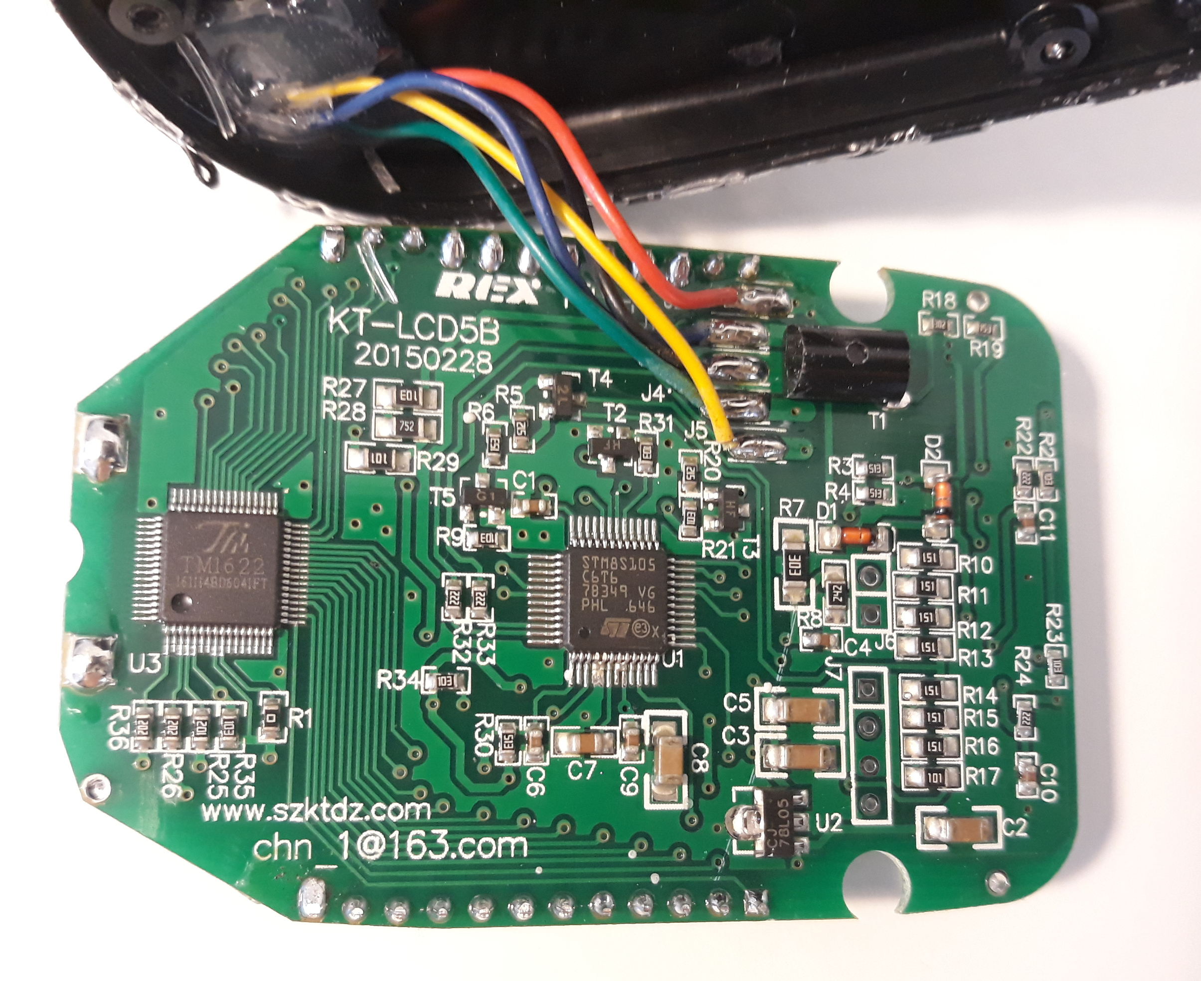
The first part of the Schematic is done (the interesting bits LOL) LCD3_display_V0_1.pdf
few interesting things i see:
PA2 needs to be logic HIGH to keep the LCD on. this works like a keep alive. write a low and the LDO loses power and turns off (i tested this behaviour)
with PE3 you can short part of the resistors before the LDO. i think this is to accomodate different input voltages.
STM8 reads the battery voltage on pin PE7. The current value is sent by the controller over UART.
Stuffing Up!
- I burn my KT LCD3, I connect 48V version to 14s battery (about 58V)
- Plug the two connectors (M to F) of the motor unit together. Blows up controller. (Hint: paint connectors with different nail varnish colors or put colored heatshrink on.)
- Use a thread lock and check the fixing of bolts more often. I missed this moment and the body broke in half