Open SW102 by cutting keypad base and solder SWD wires - OpenSourceEBike/TSDZ2_wiki GitHub Wiki
Although seems it is not possible to open this LCD without breaking/deform it, it is easy to access to the board that has the firmware programming/debug pads. Please work carefully and slowly, referring frequently to these instructions:
Leave the Up/Down keypad lid and the M button lid in place.
Cut in between the cases edge and keypad and repeating this over and over again until you can lift of the key pad by gently levering it out. You will need to run a shop knife repeatedly from left to right and top to bottom on the bottom three sides of the keypad. Don't cut in between LCD and keypad because it is very likely that the glass will break.
It helps to hold the bottom part of the case in a vice (not too tightly) so you can cut without hurting yourself or the plastic.
Cutting along the right:

Cutting along the left:

Cutting along the bottom:

After about 10 passes on each of the three sides you will feel the pressure increase because you are through the glue and now just scraping on the plastic.
At that point take a very small screwdriver (or other flat implement) and slide it vertically down into the bottom edge of the case. Try to put it about 25% in from the left side and press pretty firmly down so you can push between the bottom part of the keypad and the case. It is important to notice that the keypad comes in two parts - the top movable part with the buttons and the bottom rigid part. You want to pry only on that bottom part (see photo of the keypad below so you understand). You can pry the bottom part of the keypad up with slight but constant pressure until the remaining glue begins to unpeel. If it isn't going well, either cut some more or try prying up on the bottom edge about 25% in from the right side. Applying moderate heat (for example with a hairdryer) can also help to soften the glue.
Once the keypad begins to lift you can insert a second small screwdriver on the other side of the bottom edge to help the glue release. After the keypad is mostly out, gently pull it from the screen and the glue between it and the screen should release. Do not insert anything between the screen and the keypad or you risk breaking wires or the glass.
IMPORTANT: Notice how the keypad has a top and a bottom part. Pry up (gently) ONLY on that bottom part. Your tiny screwdriver will be pressed down between the bottom part of the keypad and the side of the case, then you will slightly pry it up to get the glue to release.

You will find the firmware programming/debug pads under the keypad plastic cover. At this point it is a good time to scrape off any remaining glue, so that when you later go to reglue the keypad (use a TINY amount of glue) you'll have a good flat base. If you leave too much old glue in, you'll find the bottom button is hard to push. Probably best to test that before reglueing the unit.

The front glass and LCD are glued, there is no way to open without breaking the case. I had to heat the plastic case and deform it until I could get the boards and LCD exposed.
If you feel you want better access for soldering, you can carefully remove the keypad circuit board from the case and use your fingernail to unlatch the ribbon cable on the back connector. You'll need to reattach the cable afterwards, but it makes it easier for you to access the pads for soldering.
If you don't have a solder iron at hand you can also program the SW102 by a solderless programming method. For this you need
- 2.54 to 2.0mm Jumper Wires** like this one
- 2.0mm pitch pin header** like this one
- 2.54 to 2.0mm Jumper Wires** like this one
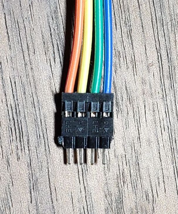
Seperate four wires and put the pin header into the 2.0mm end like on this picture:
Attach the wires to the ST-LINK as follows:
| SW102 | ST-LINK |
|---|---|
| GND | GND |
| CLK | SWCLK |
| DIO | SWDIO |
| 3V3 | 3.3V **VERY IMPORTANT NOT 5V** |
Start the Windows Tool, hit 'f' and the tool waits 10 seconds so you can get prepared by pressing the pin header against the debug pad (watch the orientation!):

If you are more into soldering you can install four wires, each about 1" long. You should select wires that fit the cable that comes with your ST-LINK programmer. You can solder these wires with the circuit board in-place if you are careful, or you can slide the circuit board out of the case for soldering, but be careful of the short ribbon cable that connects the board to the screen circuit board. Steps to follow:
- Use a very fine tip soldering iron. Something similar to this. This is especially true if you are soldering the wires with the circuit board inside the case.
- Before soldering the wires 'tin' each of the four pads with solder. By this we mean, use the tip of your soldering iron to melt a small dot of solder onto each of the pads. You can then tap that dot with your soldering iron to make sure it takes a pleasing round shape. The four pads are vertically on the right side of the keypad PCB. From top to bottom they are "GND, CLK, DIO, 3V3".
- Take your four temporary 1" long wires and tin one end of each wire with a little bit of solder.
- For each wire, hold it against the pad and heat the wire with the soldering iron until the wire and solder melt to the pad.
- Use a magnifying glass to make sure you haven't shorted any pads/wires together
- Attach the wires to the ST-LINK as follows:
| SW102 | ST-LINK |
|---|---|
| GND | GND |
| CLK | SWCLK |
| DIO | SWDIO |
| 3V3 | 3.3V **VERY IMPORTANT NOT 5V** |
- After programming (per these instructions) and once you see that the device GUI starts up, you'll know that you will never need to do this ST-LINK step again. At that point use your soldering iron to remove the four wires, close up the unit and confirm that all the buttons work before gluing the device closed again (with a tiny amount of weak glue).
