Lab 6 1,2,3: NAT - Oliver-Mustoe/Oliver-Mustoe-Tech-Journal GitHub Wiki
In these labs, we learned how to setup Static NAT and PAT in Packet Tracer.
Due to the close relation of all 3 labs, I have decided to detail all information about them here instead of on individual pages.
NOTE: Most of these commands also contain the full hostname/terminal details
Notes
Lab 6-1
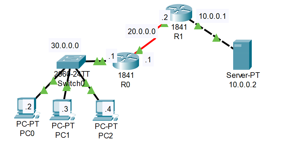
In this lab we setup a web server (10.0.0.2) to be accessible as the public IP (50.0.0.1) via NAT on Router 1.
Finished Screenshot:
First I configure Router 1 with the commands:
Router>enable
Router#configure terminal
Router(config)#hostname R1
R1(config)#interface fastethernet 0/0
R1(config-if)#ip address 10.0.0.1 255.0.0.0
R1(config-if)#no shutdown
R1(config-if)#exit
R1(config)#interface serial 0/0/0
R1(config-if)#ip address 20.0.0.2 255.0.0.0
R1(config-if)#no shutdown
R1(config-if)#exit
Then Router 0, with the commands:
Router>enable
Router#configure terminal
Router(config)#hostname R0
R0(config)#interface fastethernet 0/0
R0(config-if)#ip address 30.0.0.1 255.0.0.0
R0(config-if)#no shutdown
R0(config-if)#exit
R0(config)#interface serial 0/0/0
R0(config-if)#ip address 20.0.0.1 255.0.0.0
R0(config-if)#clock rate 64000
R0(config-if)#bandwidth 64
R0(config-if)#no shutdown
R0(config-if)#exit
Breakdown of above commands:
1 & 2. Enable and go into the config terminal
3. Set hostname
4. Config fastethernet (0/0)
5. Set ip and subnet mask
6. Enable it
7. Exit
8. Config serial
9. Ip of serial
10. Enable it (no shutdown)
11. Exit
Then I setup the desired routes on Router 1 with the command:
R1(config)#ip route 30.0.0.0 255.0.0.0 20.0.0.1
And on Router 0 with the command:
R0(config)#ip route 50.0.0.0 255.0.0.0 20.0.0.2
Here I could have Tested connectivity (on the PC's) by pinging the router addresses "20.0.0.1" and "30.0.0.1".
Then I defined the inside and outside on my NAT interfaces, on Router 1, with the commands:
R1(config)#interface fastEthernet 0/0
R1(config-if)#ip nat inside
R1(config-if)#exit
R1(config)#interface serial 0/0/0
R1(config-if)#ip nat outside
R1(config-if)#exit
Breakdown of above commands:
- Go onto fastethernet (same used above)
- Set as IP NAT inside
- Go onto serial (same used above)
- Set as IP NAT outside
- exit
Finally I created a Static Rule with the command:
R1(config)#ip nat inside source static 10.0.0.2 50.0.0.1-
- Command explained more below as I found it confusing
-
-
ip nat inside source static {IP_OF_DEVICE} {NEW_PUBLIC_IP_OF_DEVICE}
-
With all of this finished, I was able to access the webpage on the webserver from a PC with the IP of "50.0.0.1"
Below is copy pastes for R1 and R2 (can be pasted into packet tracer to fully complete above process):
R1 - COPY BLANK LINE
configure terminal
hostname R1
interface fastethernet 0/0
ip address 10.0.0.1 255.0.0.0
no shutdown
exit
interface serial 0/0/0
ip address 20.0.0.2 255.0.0.0
no shutdown
exit
ip route 30.0.0.0 255.0.0.0 20.0.0.1
interface fastEthernet 0/0
ip nat inside
exit
interface serial 0/0/0
ip nat outside
exit
ip nat inside source static 10.0.0.2 50.0.0.1
R0 - COPY BLANK LINE
configure terminal
hostname R0
interface fastethernet 0/0
ip address 30.0.0.1 255.0.0.0
no shutdown
exit
interface serial 0/0/0
ip address 20.0.0.1 255.0.0.0
clock rate 64000
bandwidth 64
no shutdown
exit
ip route 50.0.0.0 255.0.0.0 20.0.0.2
Lab 6-2
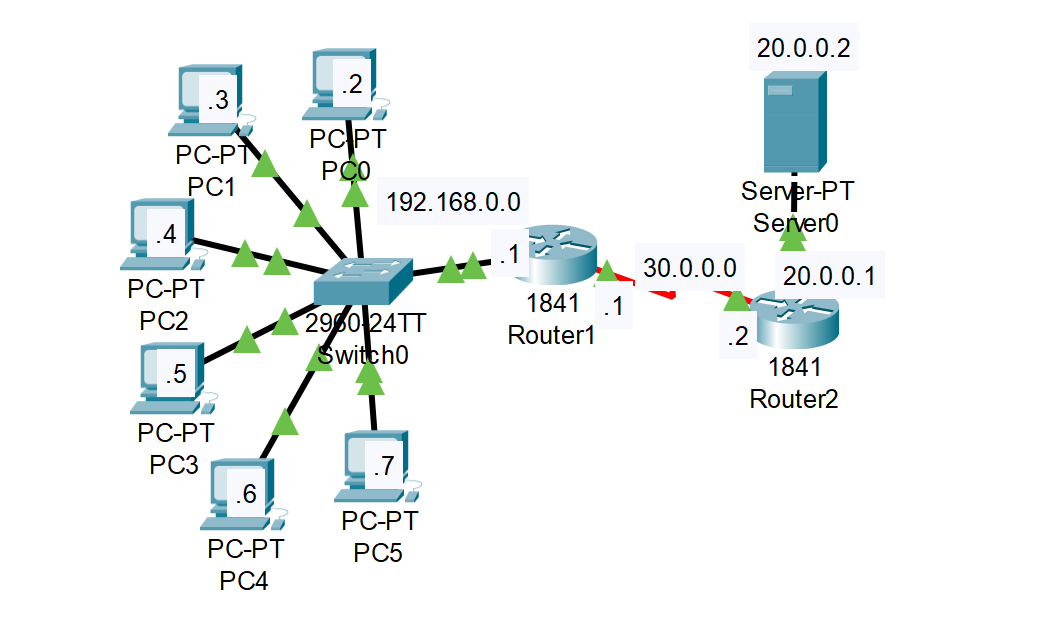
In this lab we used PAT to assign PC's on the 192.168.0.0/24 network to use the Public IP of 30.0.0.120.
Finished screenshot:
First I configured the following router interfaces -- use 6-1 as an example:
- Router 1: FE 0/0 192.168.0.1/24 and Serial 0/0/0 30.0.0.1/8
- Router 2: FE 0/0 20.0.0.1/8 and Serial 0/0/0 30.0.0.2/8
Then, on router 1, I set the Default Route (or Gateway of Last Resort) to router 2 with the command:
ip route 0.0.0.0 0.0.0.0 30.0.0.2
"A Gateway of Last Resort or Default gateway is a route used by the router when no other known route exists to transmit the IP packet." --https://www.careerride.com/Networking-gateway-of-last-resort.aspx
I then defined the "Inside" and "Outside" interfaces, see 6-1, and created a Address Pool, "test", for Public IP addresses that clients can use with the command:
R1(config)#ip nat pool test 30.0.0.120 30.0.0.120 netmask 255.0.0.0
NOTE: there is only 1 IP in this pool (30.0.0.120)
After which I would create an access-list that defines which internal IP's, 192.168.0.0 in this case, can use the Public IP pool "test" (wildcard subnet mask):
R1(config)#access-list 1 permit 192.168.0.0 0.0.0.255
Then I would assign the pool and access rule to interface with NAT statement with the command, essentially list "1" clients can use the PAT IP in "test" when going from inside to outside (overload for large amount of client usage):
R1(config)#ip nat inside source list 1 pool test overload
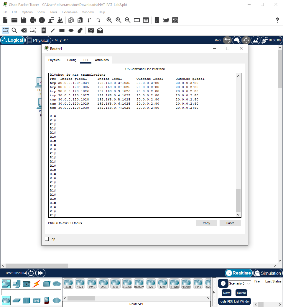
With PAT working, I was able to connect to the web service on the server 20.0.0.2 from the browser. To fully verify this process, I, on R1, used the following command to see the TCP ports used to track connections in the NAT Table:
R1#show ip nat translations
Example:
Copy pastes:
R1 - COPY BLANK LINE
ip nat pool test 30.0.0.120 30.0.0.120 netmask 255.0.0.0
access-list 1 permit 192.168.0.0 0.0.0.255
ip nat inside source list 1 pool test overload
Lab 6-3
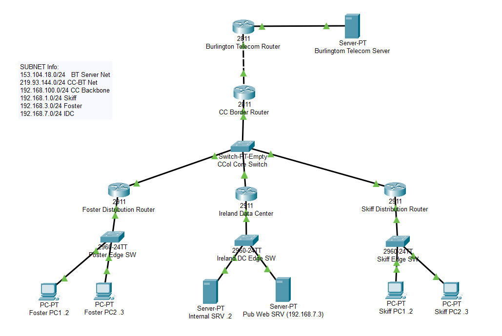
This lab required using the above 2 labs to:
- Configure PAT on CC Border Router so that Foster and Skiff PC's can ping the BT server -- lab 6-2
- Configure Static NAT on Border Router so that BT Server can access the Ireland Pub Web Server -- Lab 6-1 (no routing, just configuring Static NAT)
Because of almost entirely using other labs material, I only have the additional to add:
-
Lab given notes for PAT:
-
- Remember: Foster and Skiff are using private IP addresses (192.168....) - so they can use a shared public IP to access Internet services (such as the Burlington Telecom Server)
-
- Must demonstrate that NAT is working by showing ip nat translation table. You will need to ping the server from CC pc's to generate entries in the table
-
- Hint: access lists can have more than one network in them - just enter a "access-list 1 permit..." line for each network that is allowed (Skiff and Foster)
-
- Remember: make sure to use an IP from the Champlain Public Network as the PAT pool address
-
Change IP’s (obvious)
-
Public net is the 219 (starts with a 2) address
-
On the CC router make sure to set up default route (or Gateway of Last Resort, this is the zeros) to Burlington telecom router:
-
ip route 0.0.0.0 0.0.0.0 219.93.144.2
-
MAKE SURE TO SET THE DEFAULT ROUTE Finished screenshot: