Lab 2 1: Subnet Design - Oliver-Mustoe/Oliver-Mustoe-Tech-Journal GitHub Wiki
In this lab, we designed a network for a school in Packet Tracer.
Notes
Design Addressing
First I was given the IP allocation of 10.7.0.0/16 and filled out a addressing table seen below.
(NOTE: Columns Network, Netmask, Router Address were filled out by me. The rest was given. Also, "Router Address" = "Default Gateway")
| VLAN | VLAN_NAME | Hosts Needed | Network | Netmask | Router Address |
|---|---|---|---|---|---|
| 130 | StuLab1 | 35 | 10.7.12.64/26 | 255.255.255.192 | 10.7.12.65 |
| 140 | StuLab2 | 35 | 10.7.12.0/26 | 255.255.255.192 | 10.7.12.1 |
| 100 | FacStaff | 200 | 10.7.11.0/24 | 255.255.255.0 | 10.7.11.1 |
| 1 | Management | 250 | 10.7.10.0/24 | 255.255.255.0 | 10.7.10.1 |
| 110 | Student | 450 | 10.7.8.0/23 | 255.255.254.0 | 10.7.8.1 |
| 210 | FSWireless | 650 | 10.7.4.0/22 | 255.255.252.0 | 10.7.4.1 |
| 200 | StuWireless | 900 | 10.7.0.0/22 | 255.255.252.0 | 10.7.0.1 |
Building the network
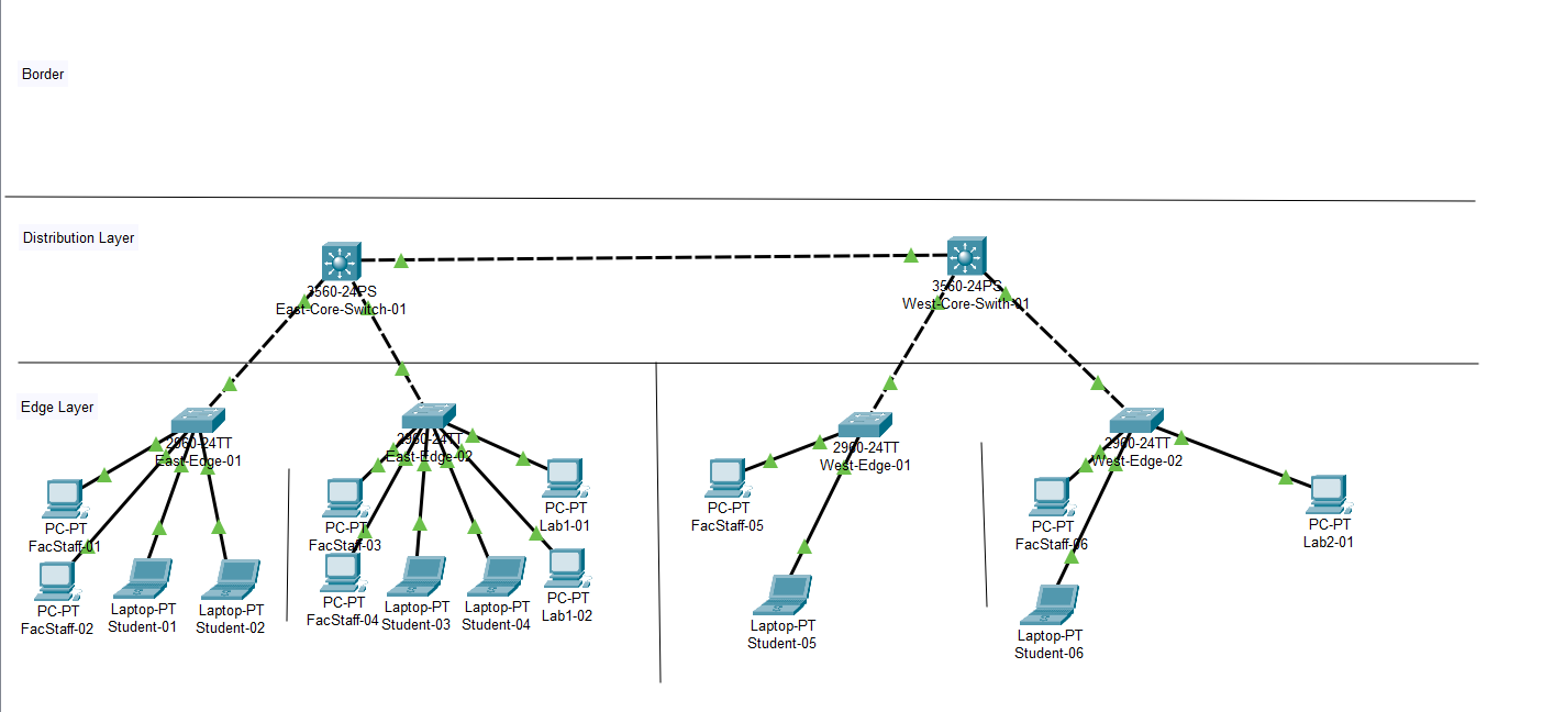
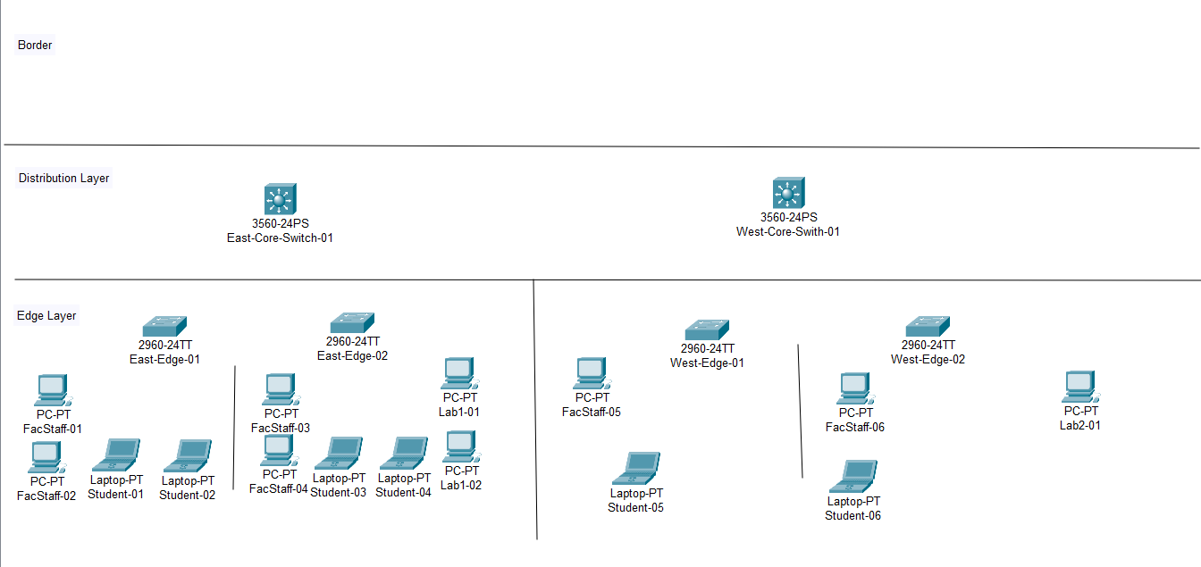
After getting the professor to check my work, I opened the assigned packet tracer file.
Below is a image of that file in the beginning:
For each Edge Switch, I added the following to the VLAN database (config > VLAN database) and added the following:
- 100 - FacStaff
- 110 - Student
And to the East-02 switch ONLY I added the following in it's VLAN database:
- 130 - StuLab1
And to the West-02 switch ONLY I added the following in it's VLAN database:
- 140 - StuLab2
(NOTE: I could have also used the following commands to configure the VLANs without GUI. For example VLAN 110:
enable
conf t
vlan 110
name Student
)
Then I set set the appropriate VLANS for the appropriate ports according to below:
- All switches = VLAN 100 (ports 4-12) and VLAN 110 (ports 13-20)
- East-Edge-02 = VLAN 130 (ports 21-24)
- West-Edge-02 = VLAN 140 (ports 21-24)
I did this through using the following commands in the switch CLI:
(config)interface range FastEthernet 0/x-y (let's you configure multiple ports at one time)
(config-if-range)switchport access vlan x (defines the vlan for all ports in the range)
For example I could use the following commands, in order, to change the VLAN 100 range:
enable
conf t
interface range FastEthernet 0/4-12
switchport access vlan 100
(NOTE: In the example file, "East-01" router contained VLAN information for VLAN 130, which it should not have. Make sure to delete it from the database and use the above commands to set ports 21-24 to 1!)
Example breakdown (from top to bottom):
- Go into privilege mode on router (Advanced user, should change router name from "router>" to "router#")
- Go to global config for the router (Configure router as a whole, should change router name from "router#" to "router(config)#")
- Define a range of ports to configure at once (Should change router name)
- Define the VLAN for the range of ports
I then did the following to each End User Device:
- Assign FacStaff PC's IP's from VLAN 100
- Assign Student PC's IP's from VLAN 110
- Assign Lab PC's appropriate IP's
(NOTE: Make sure netmask and gateway are correct, use table above for IPs from right VLANs, router address is default gateway)
I then used copper cable to attach end devices to their appropriate switches (MAKE SURE TO USE THE RIGHT PORT!!!)
Then I pinged devices on the same VLAN and the same switch, works, and pinged different VLANs and/or different switch, did not work.
I then added all of the VLANs to the "VLAN Database" on both the core switches, set "FastEthernet 0/1" & "FastEthernet 0/2" on both Core switches from "Access" to "Trunk", selecting only the VLANs I made.
On each of the Edge switches, I then set "FastEthernet 0/1" from "Access" to "Trunk", selecting only the VLANs I made and then connected the Edge switches with Cross-over cable using the their "FastEthernet 0/1" port to a available trunk port (0/1 or 0/2) on the appropriate Core switch (East or West).
To Verify this process it working, I successfully pinged between two systems on the same VLAN on different Edge switches.
I then configured the EAST-Core Switch, which is a multi-layer switch, to act as a router. To do this, I used the following commands (THE LAST TWO MUST BE REPEATED PER VLAN):
enable
conf t
ip routing
interface vlan 100
ip address 10.25.100.1 255.255.255.0
Example breakdown (from top to bottom):
- Go into privilege mode on router (Advanced user, should change router name from "router>" to "router#")
- Go to global config for the router (Configure router as a whole, should change router name from "router#" to "router(config)#")
- I turn on routing
- I go into the VLAN interface (Should add "(config-if)")
- Set the IP and netmask for the VLAN (100) on the switch
(NOTE: This only needs to be set on the router-switch acting as the gateway for the VLAN)
Hovering over the east switch, I saw the following results (highlighted in red is where the IP routing should be, ignore Gigabyte port (done later) !!!):
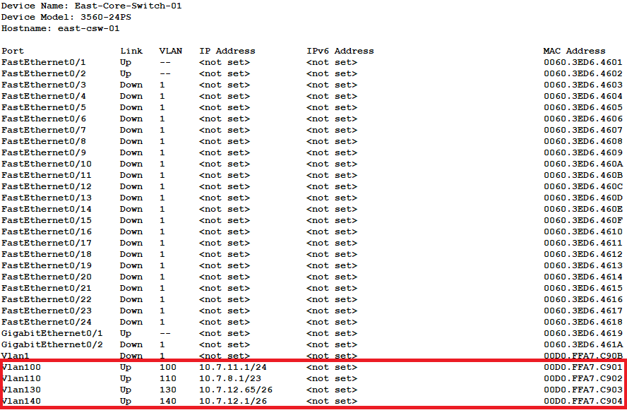
To Verify this process it working, I successfully pinged between two systems on different switches on different VLANS in the east.
I then configured "Gigabit Ethernet 0/1" on both core switches as trunk ports, only set to the VLANs I defined, and used Cross-over cable to connect those trunk ports together.
With that, I was able to ping from one end device in the network to any other end device.
Below is a picture of the completed packet tracer file.