Hypnos - OPEnSLab-OSU/OPEnS-Lab-Home GitHub Wiki
Project leads: Bao Nguyen - [email protected] | Bryson Goto - [email protected]
Long term power conservation is very important in remote sensor package deployment. Originally, the Feather M0 had a non-efficient deep sleep code and would require other sleep methods. The first solution was to completely cut the power to the Feather and its peripherals and only power back up when back into operation. However, when Adafruit releases new firmware update for Feather M0 with very low sleep current, the power circuit can now be simplified and more add ons are possible on the same footprint. The next version of OpenSPower is called Hypnos.
Hypnos has the ability to completely cut off power for peripherals while keeping the feather awake to run deep sleep code. More than just a powerboard, the Hypnos board comes with high precision real-time clock DS3231 and a microSD card for logging data during operation.
Note: Make sure you are using the Adafruit SAMD Boards version 1.5.7. Using a more recent version will prevent the SD from initializing in startup.
- Ability to fully control 3.3V rail (0.4A Continuous), 5V rail (0.5A Continuous) (if USB powered), extra V+ rail (2.0 A Continuous)
- RTC DS3231 on I2C protocol - CR1220 coin cell backup power
- MicroSD card slot (Chip Select GPIO 11)
- Header row for stacking FeatherWing using controlled power
- Optional pull-up resistor for I2C line

Here is the repo on GitHub
- Must power the 3.3Rail when communicating to the Real-Time Clock (RTC) or I2C devices. How to use this board
Any I2C device behind Adafruit I2C Multiplexer does not need to be powered. We have tested the system with the Multiplexer turn off without the I2C line hanging.
Remember to power the 3.3Rail before initializing/communicating with uSD card, RTC, and I2C devices.
-
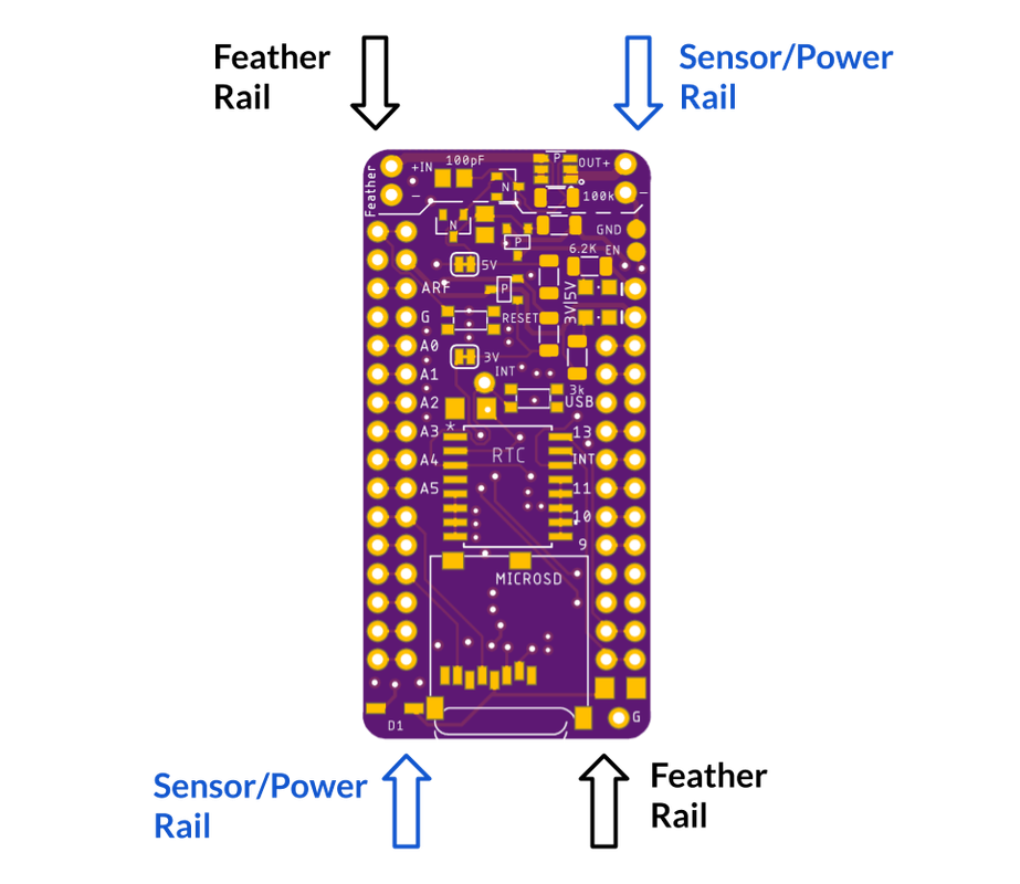
Feather Rail: connects directly to your Feather. Anything connected to this rail will have their power constantly on and only turn off in Shipment Mode. Power Control will not work on this rail.
-
Sensor/Power Rail: connects directly to your sensor board which you wish to turn the power on/off. The 5VUSB pin and 3V pin are controlled within the rail. Digital and Analog pins on this rail connect directly to the Feather. Extra 3V|5V with LEDs are for an external plug for prototyping.
-
3v3 rail: Set
PIN 5of the Feather to LOW for closed circuit (conduct), otherwise, the pin is pulled HIGH for open circuit (not conduct). -
5V rail: Set
PIN 6to HIGH for closed circuit (conduct), the PIN is pulled LOW for open circuit -
+V rail: This pin shares control with the 5V rail. Set
PIN 6to HIGH for closed circuit (conduct), the PIN is pulled LOW for open circuit
SD card: Chip Select PIN 11, required 3.3Rail power, normal SPI communication
RTC DS3231: INT-errupt PIN 12, required 3.3Rail power, I2C pull up attached to 3.3Rail
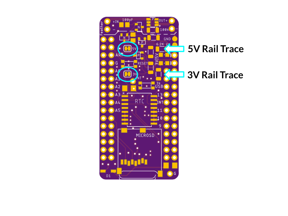
Note: If you need a GPIO pin AND you are not using one of the 3V or 5V rails, you are able to free the GPIO pin for use by cutting the trace of the rail that is not used.
Short the GND and EN will turn off the 3.3V regulator temporarily. The male header + Jumper cap is a great combination. Once the jumper cap is removed, the Feather will boot up normally and resume operation.
Quality Control

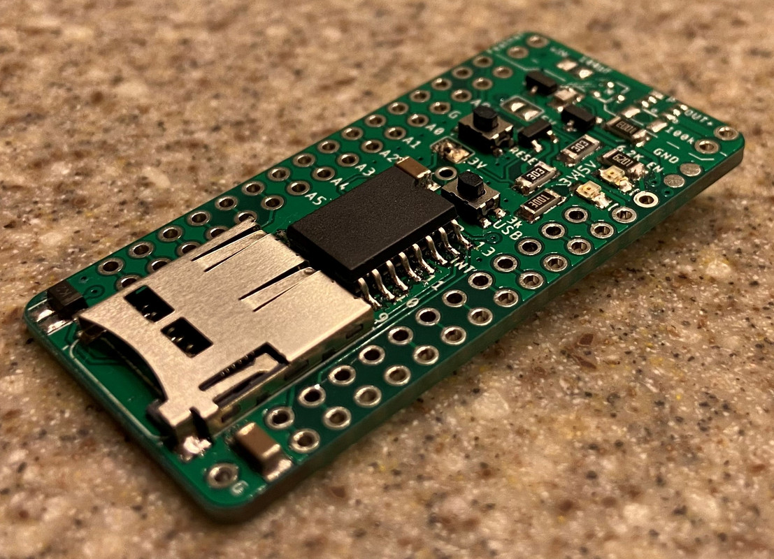
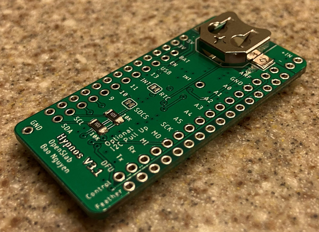
After stenciling, place components where they need. Check with the picture to see if you have placed your components correctly.
After baking, check for solder balls this size, smaller size solder balls can be ignored. Larger solder can fall off and short your circuit. Use a small tweezer to knock the ball off the board.
 |
Check for solder balls this size, smaller size solder balls can be ignored. Use a small tweezer to knock the ball off the board |
 |
Might be a cracked components or just scratched. Check value with multi-meter. If the value is good -> just a scratch, otherwise replace component |
Video for visual inspection: Youtube
The last thing to check is the microSD card slot. This is a picture of a passed solder. If there are multiple small solder balls around the pad, rework with the solder gun is required to meet quality control. Just run a solder gun with a fine cone tip and pass all of the pins a couple times. The lab uses lead-free solder so the melting point is very low so the soldering iron can be set at lower temperature (~250C).

-
- Note: We only place components and reflow one side of the board. The back components are hand-soldered after the board comes out.
Using Hypnos with Loom for Deep Sleep
At this point in time, the easiest way to interface the Hypnos with Loom is externally though the Arduino Sketch:
- In setup, as close to the beginning as makes sense, insert the following.:
pinMode(5, OUTPUT);
digitalWrite(5, LOW); // Sets pin 5, the pin with the 3.3V rail, to output and enables the rail
pinMode(6, OUTPUT);
digitalWrite(6, HIGH); // Sets pin 6, the pin with the 5V rail, to output and enables the rail
- To make ensure Loom is aware of the components on board, the following needs to be added to the config json within the 'components' array:
{\
'name':'SD',\
'params':[true,1000,11,'data',true]\
},\
{\
'name':'DS3231',\
'params':'default'\
}\
This sets up the DS3231 RTC for time stamping and interrupts, as well as the SD for reading and writing. If the SD card fails to initialize consistently, ensure your enabling the power rails as the SD needs them to function.
- Within your main loop, place the following code before and after the Loom.sleep() function:
Before:
digitalWrite(5, HIGH); // Disabling all pins before going to sleep.
digitalWrite(6, LOW);
pinMode(23, INPUT);    // Disables SPI communication to SD before going to sleep
pinMode(24, INPUT);
pinMode(11, INPUT);
After:
digitalWrite(5, LOW); // Enabling all pins after wake up has completed.
digitalWrite(6, HIGH);
pinMode(11, OUTPUT);  // Enables SPI communication to SD after going to sleep
pinMode(23, OUTPUT);
pinMode(24, OUTPUT);
This code turns off the power rails as well as turns off communication to the SD only. In order to minimize current during sleep, the pin modes need to be adjusted for all the pins that are communicating within the circuit. For example, if another sensor is communicating through SPI, the pins that are being used for that sensor needs to be set before and after sleep. The normal current reading with the Hypnos during sleep is around 0.3 mA as it is only running the RTC.
Using microSD card without Loom (least power saving)
In setup(), the SDcard needs to be turned on before SD card initialization.
pinMode(5, OUTPUT);
digitalWrite(5, LOW); // Sets pin 5 LOW to turn ON the micro SD card
Then in the beginning of loop() add the following line. This ensures if the board shuts down and restart at loop(), the SD card will turn on.
digitalWrite(5, LOW); // Sets pin 5 LOW to turn ON the micro SD card
/* Do whatever code with the SD card, sensor .... */
Then do whatever you need to do. Before going to sleep, insert:
digitalWrite(5, HIGH); // Sets pin 5 HIGH to turn OFF the micro SD card
/* go to sleep code*/