Pertinent Information Gathering by Vats (01FE21BCS249) - N-division-2021-2022-even/Repo-02 GitHub Wiki
Medicine Vending Machine
INTRODUCTION:
The medicine dispensing machine aims to provide basic medical access to places which are unreachable due to variety of factors
Some of the reasons may be:
- Unavailability of a 24x7 drug store nearby, especially in remote areas,
- The drug stores being closed or inaccessible due to bad weather or
- Unavailability of immediate help at locations like railway stations, malls, etc.
The medicine dispensing machine dispenses over-the-counter (OTC) medicines stored in it upon receiving payment for the required strip of medicine. The machine is intended to be nearly autonomous-hence, the price of the medicine is preset, and the amount placed by the customer is processed through an image processing unit placed in the machine. The advantage of the machine being autonomous is that it only requires human intervention when the medicine or cash stock needs to be refilled or replaced.
Components Used
- 230V 50Hz Supply
- Adapter 12V
- Voltage Regulator 720S
- L293D Motor Driver
- Arduino Mega
- Raspberry Pi
- Servo Motors
Approach
There are four steps the user has to go through when interacting with the machine:
- User is required to select the medicine from the switch panel on the machine
- User is required to place the price of the medicine in the cash box
- Medicine is dispensed
- Change is dispensed

Processing modules and operating flow of medicine dispensing machine
As shown in Fig 1, when the user selects the medicine they want, the machine displays the name of the medicine selected and the price of the medicine strip. The user is required to place the money in the cash box, where the image processing unit identifies the denomination of the currency. After this, the medicine is dispensed along with change, if any. The machine has been constructed using mild steel of 16 gauge (1.62 mm). This material was chosen for its ease of availability and weldability. A. Mechanism: We have used 12 motors to control the entire machine, beginning from the cash collecting up to the change dispensing. The motors were required to have a balance of speed and a torque high enough to be able to rotate the pinions of the various slider mechanisms. Motors of two different RPM have been used for different mechanisms. The distribution of motors is as follows: 1. Cash collecting: The machine utilizes four motors for this purpose. Two motors are used at the two ends of a slider mechanism to deposit the currency in the respective storage box, based on the identification of the currency. We have provided storage boxes for notes of denomination of Rs. 10, 20, 50 and 100.

A third motor, a servo has been used to transfer the amount from the cash collection box to the storage box. The fourth motor is used to move the cash collecting box between the different storage boxes. Except for the servo, all the other motors are 12V DC motors of 60 RPM, with a torque of 19.61 N-cm[3]. The servo is a 4.8V motor with a torque of 17.6 N-cm [4].Fig 2 shows a 3D model of the mechanism, made using the software Creo. 2. Medicine Dispensing: Three motors have been used to dispense the medicine. Two of the motors are connected to a slider, and push the medicine out of the medicine storage box. Five storage boxes have been provided to place the medicines inside. The medicine strips are to be stacked vertically in the boxes. Another motor has been placed in the middle of the slider, to enable the pushing mechanism to move between the medicine storage boxes, as per the user selection. These motors are also 12V DC motors, with 60RPM and a torque of 19.61 N-cm.

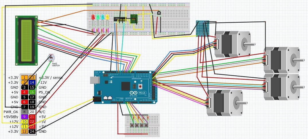
- Change Dispensing: Four motors are required by the machine to dispense the change. Each of these motors is placed in the storage boxes for the currency, and when the changes calculated, the respective motor is used to roll out the change. Any value of change (in multiples of ten) is dispensed by using these motors individually, or a combination of two or more motors, as explained in further sections. The motor which rolls out the change from the cash box is mounted at one end of a link. The other end of that link is connected to the shaft of a 12V high torque motor of 10 RPM [5] using a cotter pin. Two such links are connected to the extended shaft of a high torque motor. A cotter pin is used to compensate for the difference in the height of the stack of cash in the two corresponding boxes. This link mechanism serves two purposes: • To open up the cash box during the cash collecting stage. • To provide sufficient pressure on the notes and to house the motors that roll out the calculated change amount. The motors used to roll out the cash were of 6 RPM, taken from rotating lamps and rollers were attached to them through a link mechanism [6]. We determined the duration of the motor rotation on a trial-and-error method, as leaving the motor rotating for even slightly more time pushed more change out than required. B. Control unit: The power supply to the machine was provided using a common electrical wall outlet providing 230V (alternating current). An adapter was used to decrease the voltage to the machine from 230V to 12V (direct current), with a current rating of 1.5A.A voltage regulator-IC7805, was then used to drop the voltage to 5V, to provide for the 5V pin of Arduino and motor drivers. The Raspberry Pi has been used along with a camera module.

The Arduino Mega 2560 is a microcontroller board based on the ATMega1280, with an operating voltage of 5V, and 54 digital I/O pins [7]. A description of the Raspberry Pi has been provided later in the paper. The Arduino board receives the commands from the user interface through the Pi and controls the motors to receive the money, dispense the medicine and change as required. The motors were interfaced with the Arduino using the dual H-bridge motor driver IC L293D. The L293D IC is capable of driving up to 2 motors at a time.

The LCD (Liquid Crystal Display) used for displaying the messages on the machine was a 16x2 display LCD, with 8 data lines (D0-D7), of which D4-D7 were used for communicating with the Raspberry Pi. C. Working Principle: When the user initially interacts with the machine, a welcome message in displayed on the LCD, and the user is asked to select a medicine. The user can do so by pressing the switch corresponding to the desired medicine, on the panel. On pressing the switch, the price of the medicine will be displayed on the LCD and the user will be asked to place the amount in the cash collection box. The price of each medicine can be fed into the machine, based on the medicine that is stored inside. This allows for more flexibility in terms of the medicines available to the user. When a pressed switch is detected, the Pi instructs the camera module to capture images after a delay provided to the user to place the money. If the user has not placed the money when the image is captured, it will wait again for a short while and recapture the image. Once the user places the amount in the cash collection box, the camera module in the currency identification unit identifies the currency and its authenticity. Once the denomination is identified, the Raspberry Pi communicates the amount and medicine required to the Arduino board. If the amount received by the machine is less than the price of the medicine, the LCD will display a message asking the user to place the required amount. The Arduino board then controls the system to transfer the cash collected to its respective storage box. Next, it pushes the required strip of medicine out to the user, while simultaneously calculating whether any change needs to be returned, and if yes, the amount. If any change needs to be returned, it uses a combination of motors to retrieve the amount from the currency storage boxes.
IV. CONCLUSION: The medicine dispensing machine offers a flexible, simple and rugged solution for extending basic healthcare to all places, at a very moderate cost. The machine can be customized to suit any type of terrain or climate with minimal changes to the hardware and software. This machine will be extended to add an intelligent medicine unit, which sends a refill notification message to the nearest chemist when the number of medicine strips decrease below a certain level.
Coin Op Personal Vending Machine
This project is a step by step build of a personal vending machine. The vending machine can be filled with your favorite snacks or could be brought to the office so you can share some treats with your team.
Components Used
- Friendly Arm
- 3/4 plywood
- LFAVIN 5 sets
- Glarks 653pc dupont connector
- Bread Board
- Arduino Mega
- Led Light Strips Building the Machine I will refer to the diagrams of the machine throughout this text so please refer to the diagrams for clarification/understanding. The dimensions of the machine are 21"W x 18"D x 24 1/4"H (Box Dimensions) 2 panels 18"D x 23 3/4"H (Sides) 2 panels 21"W x 18"D (Top & Bottom)

Install the back panel and get ready for the motor installs. Make sure you have the coil wheels printed so you can measure them and setup your drill holes. Measure the wheels and add 1/4" to the height so it it will leave room for the coil to spin. You may want to adjust this as needed depending on your material. Measure over 6 1/2" on the shelf to mark its middle. Measure over 3 1/4" to find the center of each shelf section.

Use the height measurement you recorded moments ago to find the drill points. Drill a hole that will allow you to connect the wheel to the motor without the wheel shaft rubbing on the board. Finish mounting the motors and screwing in the fasteners
Shelf Dividers and Coils:
Here is how to setup your shelves and extruders.
Shelves - At the middle point 6 1/2" from the left side wall (looking at the machine from the front) or divider wall there should be a mark from the steps above. Use the flat metal and bend it into the top of a triangle. Looks just like this "^" This will serve as your middle divider. Center the triangle over the middle mark on the shelf. Repeat for the second shelf. Use hot glue to fasten in place. I put slides on the sides also but they are optional.
Coils - To create the coils first find a 1 1/2" tube. A pipe, caulk tube, spray paint can, or similar object will do. One trick is to take a rubber band and wrap it from top to bottom around the length of the tube. Trace the straight line down each side of the band on both sides of the tube. Once you have parallel lines down both sides use a tape measure to mark the next spots. Pick one side and measure in 1" and mark it, then measure 2" from there mark it and keep making 2" spaces all of the way down the tube. Now, on the other side of the tube mark only 2" intervals. Start making the coil on the 1" side of the tube and continue making your coil so it touches each mark on the both side of the tube. This will give you a 2" gap between the rungs. Should be large enough for most items. If you plan to use it for candy bard shorten the coil to 1" just reduce the formula above by half.
Connecting the coils to the 3D printed wheels. Keep in mind that there are some manufactured wheels that will work. Take a look on Amazon.
On the 1" side of the coil collapse this coil so it make a circle. Then shorten the diameter to slightly smaller then the wheel. Once the coil is ready fit it around the edge of the wheel. This should cause the coil to compress around the edge of the wheel and keep it from slipping. Once you are happy with the fit take a small dab of hot glue and put it on the wheel at the end of the coil to hold it in place.