Arduino MEGA 2560 ESP8266 WIFI - MohanadSinan/IoT-Based-Healthcare-System GitHub Wiki
 |
|---|
| Arduino Mega R3 board with ESP8266. |
Technical Specifications
| Microcontroller | ATmega328P (8 bit AVR family microcontroller) |
| Operating Voltage | 5V |
| Input Voltage (recommended) | 7-12V |
| Input Voltage (limit) | 6-20V |
| Digital I/O Pins | 14 (Out of which 6 provide PWM output) |
| PWM Digital I/O Pins | 6 |
| Analog Input Pins | 6 (A0 – A5) |
| DC Current per I/O Pin | 20 mA |
| DC Current for 3.3V Pin | 50 mA |
| Flash Memory | 32 KB (0.5 KB is used for Bootloader) |
| SRAM | 2 KB |
| EEPROM | 1 KB |
| Clock Speed | 16 MHz |
| LED_BUILTIN | 13 |
| Length | 68.6 mm |
| Width | 53.4 mm |
| Weight | 25 g |
Note: The Arduino MEGA 2560 + ESP8266 WIFI Datasheet can be found at the bottom of the page
Overview
It is a customized version of the classic ARDUINO MEGA R3 board. Full integration of Atmel ATmega2560 microcontroller and ESP8266 Wi-Fi IC, with 32 Mb (megabits) of flash memory, and CH340G USB-TTL converter on a single board!. All components can be set up to work together or independently. The convenient solution for the development of new projects requiring MEGA and WIFI Via USB you can update sketches and firmware for ATmega2560 and for ESP8266. For this onboard have the USB-serial converter CH340G.
Note: The CH340G Driver for Windows can be found at the bottom of the page
How to use Arduino Board
The board has DIP-switch, to connect the modules. There are 6 modus:
- USB <->ATmega2560: CH340 connect to ATmega2560 to upload sketch to ATmega2560
- USB<->ESP8266 (upload sketch) : CH340 connect to ESP8266 to update firmware or upload sketch to ESP8266
- USB<->ESP8266 (communication): CH340 connect to ESP8266 for serial communication
- ATmega2560<->ESP8266: Both chips can work together (after you upload the sketch)
- USB <-> ATmega2560<-> ESP8266: CH340 connect to Mega2560 COM3 connect to ESP8266 for getting Serial output when both chips working together
- All independent: Both chips working but not connected
Switch Status and Mode Selection:
| 1 | 2 | 3 | 4 | 5 | 6 | 7 | 8 | |
|---|---|---|---|---|---|---|---|---|
| ATmega2560<->ESP8266 | ON | ON | OFF | OFF | OFF | OFF | OFF | NoUSE |
| USB <->ATmega2560 | OFF | OFF | ON | ON | OFF | OFF | OFF | NoUSE |
| USB<->ESP8266 (upload sketch) | OFF | OFF | OFF | OFF | ON | ON | ON | NoUSE |
| USB<->ESP8266 (communication) | OFF | OFF | OFF | OFF | ON | ON | OFF | NoUSE |
| USB <->ATmega2560<->ESP8266 | ON | ON | ON | ON | OFF | OFF | OFF | NoUSE |
| All independent | OFF | OFF | OFF | OFF | OFF | OFF | OFF | NoUSE |
Note 1: USB converter CH340G connect to RX0/TX0 of ATmega2560
Note 2: ESP8266 connect to RX3/TX3 of ATmega2560
Also, have switch for change of connecting port between ATmega2560 and ESP8266

After choosing the mode of the board can proceed to set up the IDE
It is important that when the ESP8266 module is programming, it is necessary to press the button “Mode”

To begin open the Arduino IDE programming environment and go to settings

Then in the window that appears in the row, Additional Boards Manager URLs (marked in red) insert http://arduino.esp8266.com/stable/package_esp8266com_index.json link for installation in Arduino IDE additional scripts that would work with the modules ESP8266 and click OK

Then go to the Tools> Board> Boards Manager

In the window that appears, scroll through the list down to the script esp8266 by ESP8266 Community and click.

In the lower right corner will be able to select the version of the software, select the version 2.1.0 (the newest) and click the Install button

After installation, close the window and go to Tools> Board and see the list of available devices on the chip programming ESP8266

Next, you need to select the card as shown in the picture (Generic ESP8266 module)

Select the upload speed - 115200

Code
Test sketch for ATmega2560
 void setup()

{

  Serial3.begin(115200);

  pinMode(13,OUTPUT);

  delay(500);

  Serial3.println("AT+CIPMUX=1");

  delay(2000);

  Serial3.println("AT+CIPSERVER=1,5000");

  delay(2000);

  Serial3.println("AT+CIPSTO=3600");

  delay(2000);

}


void loop()

{

   while(Serial3.available())

  {

    char Rdata;

    Rdata=Serial3.read();

    if(Rdata=='A'|Rdata=='a')

    {

      digitalWrite(13,HIGH);

      delay(50);

    }

    else if(Rdata=='B'|Rdata=='b')

    {

      digitalWrite(13,LOW);

      delay(10);

      digitalWrite(13,HIGH);

      delay(10);

      digitalWrite(13,LOW);

    }

    else

    {

      digitalWrite(13,LOW);

    }

  }

}
AT Firmware Installation
If you want to use ESP8266 in AT mode, download the PDF file. You should now configure the card so that the ESP8266 is connected to the USB and in recording mode. To do this, set switches 5, 6, and 7 to ON (left) and all other switches to OFF (right).
| 1 | 2 | 3 | 4 | 5 | 6 | 7 | 8 | |
|---|---|---|---|---|---|---|---|---|
| USB<->ESP8266 (upload sketch) | OFF | OFF | OFF | OFF | ON | ON | ON | NoUSE |
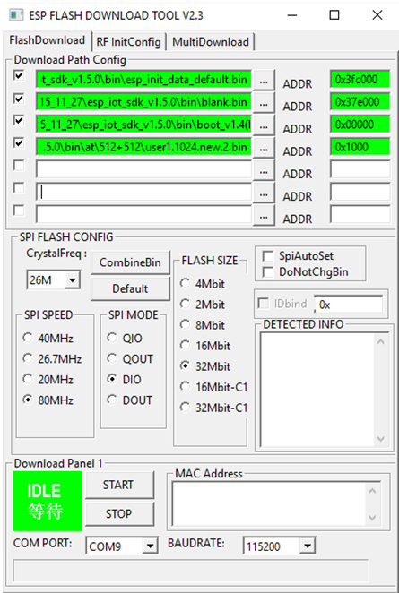
If you want to use ESP8266 in AT mode, you should use esptool.exe, which is a command tool that accesses the ESP8266 Flash and checks for some settings, such as the chip type and memory size. Configure the Flash Download Tool as follows:
- SPI Speed = 80MHz
- SPI Mode = DIO
- Flash Size = 32Mbit 4mb bytes x 8 bits = 32m bits
- Crystal Freq = 26M
- File\bin\esp_init_data_default.binataddress0x3fc000
- File\bin\blank.binataddress0x37e000
- File\bin\boot_v1.4(b1).binataddress0x00000
- File\bin\at\512+512\user1.1024.new.2.binataddress0x1000