workshop advanced - MobiFlight/MobiFlight-Connector GitHub Wiki
[!CAUTION] This guide is obsolete. See the updated guide for information on building the advanced workshop project.
Workshop - Advanced
The workshop is aimed at everyone who would like to try out building their first device with MobiFlight for enhancing their flight simulation experience. For the configuration, advanced MobiFlight techniques and concepts are demonstrated. Prior experience is beneficial, but not necessarily required.
Overview
You will build a device that uses
- Buttons
- LCD Display
- Dual Encoder
You will learn how to configure these devices and how to assign functions inside the simulator so that you can interact with it.
You can download an example solution for MSFS2020 or X-Plane for the config, in case you get stuck.
Required parts
- 1x Arduino
- 1x MobiFlight Prototyping board
- 1x USB cable
- 1x body incl 3x lids
- 1x Dual Encoder Kit
- 1x LCD Display
- 1x Micro-switch PCB
- 1x Switch pad
- 1x MobiFlight Switch PCB
- XH-JST-Wires: 1x 3-pin, 1x 4pin, 2x 4pin (included in Dual Encoder Kit)
- 12 screws (5mm M3)
3d print files (STLs)
- Base / Core - workshop-advanced-base.stl
- Two button lid - workshop-lid-buttons-2.stl
- Two button insert - workshop-lid-buttons-2-insert.stl
- Four button lid - workshop-lid-buttons-4.stl
- Four button insert - workshop-lid-buttons-4-insert.stl
- LCD lid - workshop-lid-lcd.stl
- Dual Encoder lid - workshop-dual-encoder-lid.stl
- Honeycomb/Saitek adapter - honeycomb-adapter-short.stl
For downloading, hover mouse over filename >
right-click>Save file as
Exploring the prototyping board

The prototyping board is a great way to learn about MobiFlight and connecting different device types easily and without soldering.
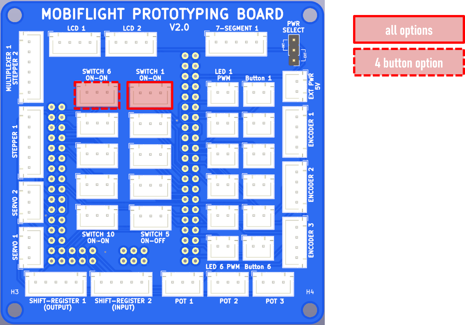
In the workshop we are going to use the highlighted connectors:
LCD 1- for the connector on the LCD DisplayEncoder 1- for the 1st connector on the dual encoder PCBEncoder 2- for the 1st connector on the dual encoder PCBSwitch 1 (ON-ON)- For the first connector on the micro-switch PCB
for 4-button option, additionally:
Switch 6 (ON-ON)- For the second connector on the micro-switch PCB
Assemble Arduino and Prototyping board
- Insert Arduino board on the back of the PCB
- Connect the cable
- Connect the cable to your computer
Note: for those who have not brought their computer, they can use one of our laptops, or we can flash it after the session
Start MobiFlight Connector
- Download MobiFlight Connector from the website
- Install MobiFlight by following the instructions of the installer
- Start Mobiflight, see what’s happening
- attempt to auto upload firmware
- Arduino Mega Pro mini is ambigious
- Manually upload firmware
- right click on module and select
Upload firmware>Arduino Mega 2560
- right click on module and select
- Save the prepared config
- Open the config, right click on module >
Open - Explore the devices
Assemble Micro-Switch Lid

- Insert the buttons into the lid
- Add the PCB from the back
- Fasten the PCB with screws
- Plug in the 3-pin wire, pass it through the back
- Close the lid
Hint: The lid will slide on with pressure. For releasing the lid again, push from the back.
Connect Micro-Switches
- Use 1x 2-pin cable
- Connect switch PCB
Connector 1toSwitch 1 ON-ON
4 button option:
- Use 1x 2-pin cable
- Connect switch PCB
Connector 2toSwitch 6 ON-ON
Assemble LCD

- Unpack the LCD Display
- Fasten screws to attach LCD to the back of the lid
- Connect the 4-pin wire to the back of the LCD display Make sure to connect the black wire to the GND pin
- Put the wire through the back
- Close the lid
Connect LCD
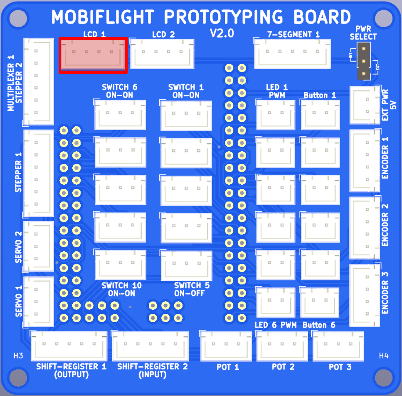
- Use 1x 4-pin cable
- Connect LCD to
LCD 1
Assemble Dual Encoder

- Put the Encoder PCB on the back of the lid
- Fasten it with the screws
- Put the wire through the back Bend them 90 degress close to the connector for better fit inside the housing
- Close the lid
Connect Dual Encoder

- Use 2x 4-pin cable
- Connect Encoder PCB
Inner ShafttoEncoder 1 - Connect Encoder PCB
Outer ShafttoEncoder 2
Configuration
During this workshop, we are going to use COM1 & COM2:
- Dual Encoder for changing MHz and KHz of standby frequency (outer and inner knob), (input configuration)
- Dual Encoder push function to swap active and standby frequency, (input configuration)
- LCD Display to show the information about
activeandstandbyfrequency, (output configuration) - Two buttons to scroll through the different pages
- Page 1 - shows COM1
- Page 2 - shows COM2
Getting ready
- Connect the Arduino, and make sure that all steps are done
- Start MSFS2020
- Start MobiFlight
Dual Encoder COM1 MHz/KHz - Input configuration
First we want to configure that the the dual encoder knobs control the value of the COM1 active and standby frequency using the outer and inner knob respectively:
- Click on
Input configstab - Create input config for MHz
COM1 MHz - Click
...to open the Input Config Wizard dialog- Click
Scan for input - Turn the outer knob of the dual encoder, MobiFlight will detect the encoder
- Click
On Lefttab, to define the action for turning left - Select Action Type
Microsoft Flight Simulator - Search for
COMand filter AircraftGenericand SystemRadio - Select
COM_RADIO_WHOLE_DECfrom the preset list - Click the
Copybutton - Click the
On Righttab, to define the action for turning right - Click the
Pastebutton - Select
COM_RADIO_WHOLE_INCfrom the preset list
- Click
- Click
OKto close the Input Config Wizard
Turn the outer knob and watch how the MHz part of the COM1 standby changes in the virtual cockpit.

Now we will create a similar configuration for your inner knob.
- Right click on
COM1 MHzconfig item- Select
Duplicate rowfrom the context menu
- Select
- Click into the description field
COM1 MHz (Copy)and change the name toCOM1 KHz - Click
...to open the Input Config Wizard dialog- Click
Scan for input - Turn the inner knob of the dual encoder, MobiFlight will detect the encoder
- Click
On Lefttab, to define the action for turning left - Change
COM_RADIO_WHOLE_DECtoCOM_RADIO_FRACT_DEC - Click the
On Righttab, to define the action for turning right - Change
COM_RADIO_WHOLE_INCtoCOM_RADIO_FRACT_INC
- Click
- Click
OKto close the Input Config Wizard
Turn the inner knob and watch how the KHz part of the COM1 standby changes in the virtual cockpit.
Dual Encoder frequency swap - Input configuration
Now use the dual encoder's push button function (inner knob) to swap the standby and active frequency:
- Create input config for MHz
COM1 Swap - Click
...to open the Input Config Wizard dialog- Click
Scan for input - Push the inner knob of the dual encoder, MobiFlight will detect the button
- Click
On Presstab, to define the action for depressing the button - Select Action Type
Microsoft Flight Simulator - Search for
COMand filter AircraftGenericand SystemRadio - Select
COM_STBY_RADIO_SWAPfrom the preset list
- Click
- Click
OKto close the Input Config Wizard
Push the inner knob and see how the standby freuqency becomes the active frequency and vice versa.
LCD Display - Output configuration
First, we will read the correct value from the sim:
- Click on
Output configstab - Create output config for COM1
COM1 Active - Click
...to open the Output Config Wizard dialog - On
Sim Variabletab- Select variable Type
Microsoft Flight Simulator 2020 - Search for
COMand filter AircraftGenericand SystemRadio - Select
COM ACTIVE FREQUENCY:indexfrom the preset list - Select
1in select index popup, since we are interested in COM1
- Select variable Type
- Click
OKto close the Output Config Wizard - Test the config
- Click on the green play button in the toolbar
- Check the
Flight Sim Valuecolumn, the value there should match the current value of the aircraft - Use the push button to swap the frequencies, the value should update accordingly
Now that we know that we are using the right value, let's display it on the LCD screen
- Click
...to open the Output Config Wizard dialog - On
Displaytab- Select
Protoboard v2as module - Select type of
LcdDisplay - Select
LCD1for display - use the
Test-button, the default text will show on the screen - update the test value to
121500 - update the LCD text with
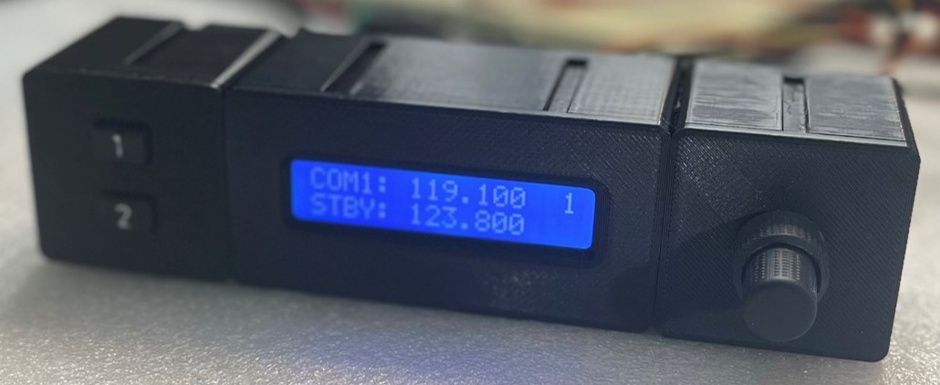
COM1: $$$.$$$ - check the display, it will show
COM1: 123.450
- Select
- Click
OKto close the Output Config Wizard - Test the config
- Verify that the active frequency is displayed correctly
- Use the push button to swap the frequencies, the value should update accordingly
The
$character is subsituted automatically with the current value of the config.

LCD Display - Config reference feature
Now we will add the COM1 Standby frequency. For this we will create a new config COM1 Standby which we will later display together with COM1 Active on the LCD. For this you will make use of the Config reference feature
- Create new output config for COM1
COM1 Standby - Click
...to open the Output Config Wizard dialog - On
Sim Variabletab- Select variable Type
Microsoft Flight Simulator 2020 - Search for
COMand filter AircraftGenericand SystemRadio - Select
COM STANDBY FREQUENCY:indexfrom the preset list - Select
1in select index popup, since we are interested in COM1
- Select variable Type
- Click
OKto close the Output Config Wizard - Verify that
Flight Sim Valuecolumn shows the correct value - Go back to
COM1 Active - Click
...to open the Output Config Wizard dialog - On
Modifytab- Click
Add reference - Select
COM1 Standby - Activate the checkbox (tick)
- Use
#as placeholder character
- Click

- On
Displaytab- Add a second line to the LCD text
STBY: ###.###
- Add a second line to the LCD text
- Click
OKto close the Output Config Wizard - Test the config
- Verify that the active frequency is displayed correctly
- Verify that the standby frequency is displayed correctly
- Use the push button to swap the frequencies, the value should update accordingly
With
config referencesyou can define additional characters which are subsituted automatically with the current value of the respective config.
Duplicate configs for COM2
You will copy all configs for COM1 and adapt them for COM2. First the output configs and then input configs.
Duplicate output configs for COM2
- Click on
Output configstab - For the two config items
COM1 Active,COM1 Standbydo- Right-click on the config item
- Select
Copyfrom the context menu - Select the last config item in the list
- Right-click to bring up the context menu
- Select
Paste, which will paste a copy after the selected row - Edit the description and change
COM1forCOM2, and remove(Copy)
Your output configs should look like this:

Now edit all COM2 related configs, and for each:
- On
Displaytab- Change
COM1related sim variable to the correspondingCOM2versionCOM ACTIVE FREQUENCY:index-> Select index2COM STANDBY FREQUENCY:index-> Select index2
- Change
- On
Modifytab (only forCOM2 Activeconfig)- Use
COM2 Standbyas config reference
- Use
- Click
OKto close the Output Config Wizard
Watch the LCD Screen closely, it will start to flicker. This is because the LCD is quickly displaying two different values. Check the Flight Sim Value, there it will show the correct values.
Temporarily deactivate one group (either COM1 or COM2) by clicking the Active check box.
Duplicate input configs for COM2
Similar to the output configs, do the following
- Click on
Input configstab - For the three config items
COM1 MHz,COM1 KHzandCOM1 Swapdo- Right-click on the config item
- Select
Copyfrom the context menu - Select the last config item in the list
- Right-click to bring up the context menu
- Select
Paste, which will paste a copy after the selected row - Edit the description and change
COM1forCOM2, and remove(Copy)
Now edit all COM2 related configs, and for each:
- On
Displaytab- Change
COM1related sim variable to the correspondingCOM2versionCOM_RADIO_WHOLE_DECtoCOM2_RADIO_WHOLE_DECCOM_RADIO_WHOLE_INCtoCOM2_RADIO_WHOLE_INCCOM_RADIO_FRACT_DECtoCOM2_RADIO_FRACT_DECCOM_RADIO_FRACT_INCtoCOM2_RADIO_FRACT_INCCOM STANDBY FREQUENCY:index-> Select index2
- Change
- Click
OKto close the Input Config Wizard
Temporarily deactivate one group (either COM1 or COM2) by clicking the Active check box. You can now either change COM1 or COM2 values.
As a last step, instead of activating or deactivating the configs, we will use our buttons to switch through multiple virtual pages for our LCD and making sure that our encoder only changes the correct COM1 or COM2 setting.
Buttons, variables, preconditions
To create multiple pages with their own information (e.g., COM1 vs COM2) we will apply two additional concepts:
- MobiFlight variables - which is a place where we can store information independently of the sim
- Preconditions - you define a condition that has to be true and only then Mobiflight will evaluate the config completely, if not true the configuration will be skipped.
Button - input configuration
- Click on
Input configstab - Create input config
Page Up - Click
...to open the Input Config Wizard dialog- Click
Scan for input - Push a button which will be used to scroll through the pages
- for the 2-button version, use button
1, - for the 4-button version, use button
^
- for the 2-button version, use button
- Click
On Presstab, to define the action for depressing the button - Select Action Type
MobiFlight - Variable - Use type
Number, namePageand valueif($=1,0,$+1)
- Click
- Click
OKto close the Input Config Wizard
- Click on
Output configstab - Create new output config for page-variable with name
Page - Click
...to open the Output Config Wizard dialog - On
Sim Variabletab- Select variable Type
MobiFlight Variable - Select type
Stringand NamePage - Click
OKto close the Output Config Wizard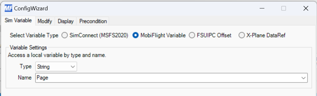
- Select variable Type
- Test the config
- Push the page up button
- Check that the
Flight Sim ValueforPageshows a value of 0 and 1, alternating with every push
You can figure out how to do the same for the page down button, just use if($=0,1,$-1) instead.
Preconditions - output configuration
- Click on
Output configstab - For the config item
COM1 Activedo- Click
Preconditiontab - Select precondition
- Use type of
MobiFlight Variable - Choose variable
Page - Set if current value is
=and0(0is our first page index)
- Click
- Click
OKto close the Output Config Wizard - For the config items
COM2 Activedo- Click
Preconditiontab - Select precondition
- Use type of
MobiFlight Variable - Choose variable
Page - Set if current value is
=and1(1is our second page index)
- Click
- Click
OKto close the Output Config Wizard
- Test the config
- Push the page up button
- You will see exclamation marks in front of one of the configs, depending on the Page value being 0 or 1
- Hover with the mouse over an exclamation mark, it will say
Precondition not satisfied - Check the LCD screen, it won't flicker anymore because it displays only one page at a time
Preconditions - input configuration
- Click on
Input configstab - For the config items
COM1 MHz,COM1 KHz,COM1 Swapdo- Click
Preconditiontab - Select precondition
- Use type of
MobiFlight Variable - Choose variable
Page - Set if current value is
=and0(0is our first page index)
- Click
- Click
OKto close the Output Config Wizard - For the config items
COM2 MHz,COM2 KHz,COM2 Swapdo- Click
Preconditiontab - Select precondition
- Use type of
MobiFlight Variable - Choose variable
Page - Set if current value is
=and1(1is our second page index)
- Click
- Click
OKto close the Output Config Wizard - Test the config
- You will see exclamation marks in front of some configs, depending on the Page value being 0 or 1
- Use the outer and inner knob and see how it only affects either COM1 or COM2
- Hover with the mouse over an exclamation mark, it will say
Precondition not satisfied
Congratulations! You did it. You learned a lot during this workshop:
- Configure encoder inputs
- Configure LCDs with multiple values
- Use MobiFlight variables
- Use Preconditions
What to do next?
- Take your device home
- Play around with assigning functions
- Watch the Getting started video
- Join our MobiFlight Discord Server
- Check out our MobiFlight Community Shop
- Build your own things!