Mobiflight Connector Main Window - MobiFlight/MobiFlight-Connector GitHub Wiki


The menu bar contains the following items
-
File

- New - Create a new MF Config file
- Open - Open MF config file
- Merge - Merge two MF config file
- Save As - Save a copy of current MF config file
- Recent Documents - Open a config file from your list of recently opened files (the number of files can be configured in the settings dialog)
-
Extras

- Hubhop - Download latest presets to update the MSFS2020 events database
- Microsoft Flight Simulator - Install the WASM module for Microsoft Flight Simulator and update legacy "events.txt" file.
- Copy logs to clipboard - Copies the MobiFlight logs to the clipboard for easy sharing in Discord support discussions
- Manage Orphaned serial - Opens dialog to manage orphaned serials of Arduino and Arcaze modules in current config
- Settings- Mobiflight-Connector main settings
-
Help

- Open help in web - brings you to the current website
- Check for update - checks on the internet if updates are available
- Join Discord Server - open the Mobiflight Discord server in your browser
- Visit HubHop Website - open the HubHop main page in your browser
- Visit Youtube Channel - open the Mobiflight Youtube Channel in your browser
- About - Information about current software version
- Release notes - Notes about the latest release

- Save - save the current configuration. It is enabled if there are changes made to the current configuration.
- Run - executes the current configuration. It is only clickable if supported modules are recognized (MobiFlight Board or Arcaze) and your flight sim is running
- Test - executes the Test Mode. For each configuration item the test mode is toggled. With this function you can check that your configuration is addressing the correct output device. It helps most with LEDs and 7 segment displays
- Stop - Stops the currently active mode (Run/Test).
- AutoRun - Can be activated and then runs MF Connector automatically on next start using the last loaded Configuration (Run-Mode). The application minimizes to the taskbar and it waits until the connection to your flight sim becomes available. The start order (MFConnector vs flight sim) does not matter.
- MobiFlight Modules - Direct access to the settings dialog for the MobiFlight modules
- Donate - Donate to the MobiFlight project using this button.
- Discord - Opens the MobiFlight Discord Server
- HubHop - Opens HubHop in your default browser.
- YouTube - Opens the MobiFlight Channel on YouTube in your default browser.
- Exit- Closes the application. If there are still unsaved changes, you will see a message that informs you and gives you the possibility to first save your changes or discard them - as you like.

The configuration list on the output tab shows you all entries of the currently loaded file (see file name in title bar). The config list items contain the following information:
- Active - the config item is activated. Only active config items are executed during "Run"-mode and "Test"-mode.
- Description - You can assign a meaningful name for each config item. Double click on the field in the desired row to activate edit mode.
- Module - The the name of the used module. You can sort configs by this column. If no output device is configured and no module is selected then this value will be empty.
- Output - the name of the device that used in the configuration. You can sort configs by this column. If no output device is configured then this will be empty.
- Type - the type of the device that is used in the configuration. You can sort configs by this column. If no device is configured then this will be empty.
- Flight Sim Value- The last raw value which has been received from the sim or which has been stored in a MobiFlight variable. Only up-to-date if MobiFlight is connected to the flight sim and running ("Run"-Mode).
- Output Value - Current value which is used for the output device. This value can vary from the original raw value according to the rules you configure in the Config Wizard (Transform, compare, interpolation).
- ...- Click on the button to access the Config-Wizard (see. 2.). You can also open the Config-Wizard by double clicking on the row.
-
Config line operations

- Copy Copy the selected row.
- Paste Paste the copied row in the selected location.
- Duplicate row Create a new row with identical parameters to the selected row (like copy/paste combined).
- Delete row(s) Delete the selected row(s)
- Drag and Drop As of Beta version 9.7.1.9, you can drag and drop output config lines to change their position in the list.

The configuration list on the inputs tab shows you all entries of the currently loaded file (see file name in title bar) concerning input configuration. The config list items contain the following information:
- Active - the config item is activated. Only active items are considered and evaluated when running the software.
- Description - You can assign a meaningful name for each config item. Double click on the field in the desired row to activate edit mode.
- Module - The name of the module used in the configuration. You can sort configs by this column.
- Input - It shows the name of the used input device and the module's name. You can sort configs by this column.
- Type- The type of input device. You can sort configs by this column.
- ...- Click on the button to access the Input-Config-Wizard (see. 3.). You can also open the Input-Config-Wizard by double clicking on the row.
-
Config line operations
- Copy Copy the selected row.
- Paste Paste the copied row in the selected location.
- Duplicate row Create a new row with identical parameters to the selected row (like copy/paste combined).
- Delete row(s) Delete the selected row(s)
- Drag and Drop As of Beta version 9.7.1.9, you can drag and drop output config lines to change their position in the list.
In both lists, outputs and inputs, you can sort the current view by clicking on the column header. The sort order is ascending, descending, reset sorting. The sorting of the items will not be reflected on saving. This means the order in the config file will be the same as when no sorting is active.
To change the actual order of the config items, you can drag 'n drop individual single lines. The new order will also be persisted on saving the config.
Drag 'n drop doesn't work when sorting is active. Reset sorting first, and then rearrange config items.
Found at the bottom left corner of the Mobiflight window.

-
Connected devices- Shows the status of currently connected modules, joysticks, and MIDI devices. You can click on a module to directly access the MobiFlight board settings dialog.

- yellow - No supported module, joystick, or MIDI device found
- green - at least one supported module, joystick, or MIDI device has been recognized on your PC
-
Sim Status- indicates the status of your flight sim connection.

- yellow - There is no flight sim connection - Possible reasons:
- your flight simulator has not been started yet,
- your flight simulator has not started the connection interface (e.g. SimConnect, FSUIPC).
- for SimConnect - the WASM module is not started, make sure it is installed correctly.
- green - MobiFlight is successfully connected to your flight sim
-
Aircraft profile status - Indicates the currently loaded aircraft in the simulator

- Green - The linked profile for the current aircraft in the simulator is loaded.
- Link current config. Active when the current profile loaded in Mobiflight is not linked to the current aircraft loaded in the simulator. Pressing will link this profile to the current aircraft loaded.
- Open linked config. Active if the current aircraft loaded in the simulator has a linked profile, not currently loaded.
- Remove link. Deletes the link between the current aircraft and the current profile.
- Auto-load linked config. Will automatically load the linked profile whenever the linked aircraft is loaded in the simulator.
-
Status Info... - Bottom right corner of the main Mobiflight window. It indicates status of your execution mode

- "Status Info..." - The software is currently not in Run Mode. You stopped it or an have not yet started it. While not running, the FSUIPC values will and attached devices will not be updated.
- "Running..." - Currently MobiFlight Connector is in "Run-Mode". Values are read from and written to FSUIPC, output and input devices are also updated. Hint: As long as the little dots move around, the application is running fine. Should they stop to move it is likely that an error occured and the "Run mode" stopped or the application has to be restarted (latter case happens only very rarely).
- Hubhop last update - NEW FEATURE The date shown next to the Hubhop logo is the date of the last event database update.
The settings dialog provides access to general and module specific configuration options. You can access the settings dialogue via the main menu "Extras" > "Settings".
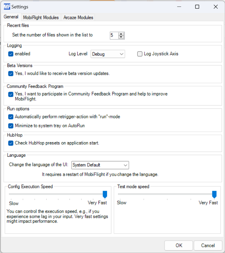
The following options can be configured on the general settings tab:
-
Recent files -
Set the number of files which are shown in the recent files list- 5 is default. -
Logging - if you experience problems with the software it might be helpful to
enablethe logging mode and set theLog levelto info or debug. You can later provide the information on the forum so that the cause of the problem can be found more easily. - Beta Versions - Activate the option to participate in the beta program. You will receive update notification when a new beta version has been released. Have in mind that beta-versions are not as stable as official releases.
- Community Feedback Program - Activate the option to participate in the MobiFlight Feedback Program
-
Run Options
-
Automatically perform retrigger action with "run"-mode- Will automatically send your panel switches status to the simulator when entering Run mode. -
Minimize to System Tray on Autorun- Will minimize the Mobiflight window to the System Tray after starting, if Autorun is activated.
-
-
HubHop
-
Check HubHop presets on application start- Will automatically check your local HubHop database for age. If older than 7 days, it will remind you to update your database during startup.
-
-
Language - You can select the language for the UI. A change will require a MobiFlight restart.
-
System Default- Your current system settings -
English- English interface -
German- German interface
-
-
Config Execution Speed - You can control the general execution of MobiFlight. The setting determines how often MobiFlight will execute your output configs. Slow is every 250ms, very fast is every 50ms. It is recommended to set this value to
Very Fast. - Test mode speed - If you have a larger number of output config items then it makes sense to change this to a faster value. Default is slow (1 second per row).

On the "MobiFlight Modules"-Tab you can configure your mobiflight boards. You can:
- Flash a stock arduino board so that it turns into a MobiFlight boardSee the firmware update documentation for details
- You can configure your MobiFlight board by adding or removing devicesSee the tutorials section for the different device types
Modules context menu
Right clicking on a module icon brings up this context menu

- Add device - Create a new device entry for this board
- Remove device - Delete a device entry in this board
- Upload Config - Upload the current device config to the board
- Open - Load a device config from a backup file (mfmc)
- Save As... - Save the current device config to a mfmc file
- Update Firmware - Install or reload the Mobiflight firmware to this board
- Regenerate Serial - Regenerate a new serial number for this board
- Reload Config - Reload to MF Connector the config stored in the board's EEPROM
- Reset Board - Factory reset the board (loads blink sketch)
- Ignore COM port - Specify which COM ports should not be scanned by Mobiflight
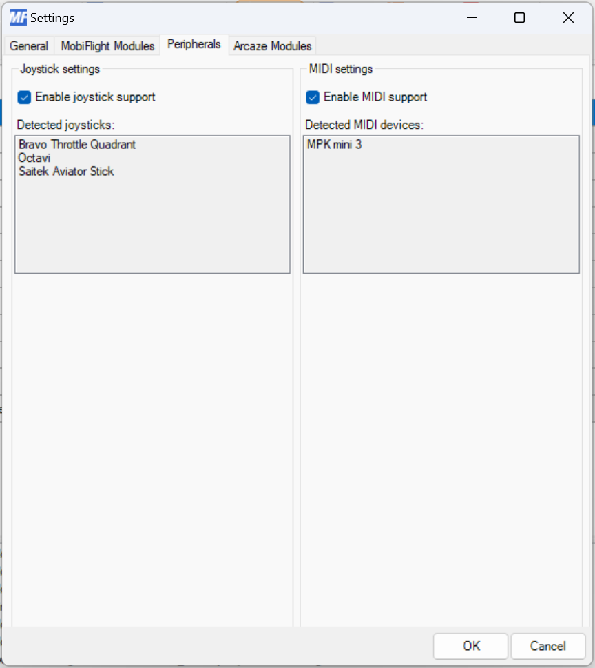
On the "Peripherals"-Tab you can see all Joysticks and Midi-devices that have been detected by MobiFlight. More options are planned for the future, e.g. deactivate support for a specific midi-device in case it conflicts with another application.
On the "Arcaze Modules"-Tab you can configure extension modules that you use on your aracze modules, like LED Driver v2 / v3 / v32 or Display Driver. If none is connected the Extension Type is called "InternalIO"
- Available Arcaze Modules, a list with currently connected Arcaze modules, that you can configure.
-
Module Settings - In this section you provide the information about the extension modules. This is needed so that the extension modules are initialized correctly and everything works as expected.Click on the desired arcaze module in the list on the left and then choose from the following options:
- Type - InternalIO, DisplayDriver, LedDriver2 oder LedDriver3
- Count - the number of connected modules at the Arcaze-Board
- Global Intensity - The globale intensity of the LEDs, only available for Display Driver and LED Driver 3/32
The Config-Wizard let's you to edit your configuration items in a user friendly and convenient way by distributing different aspects of the configuration over different tabs. You can open the Config Wizard with the following actions:
- Click on "..."-Button in "Outputs"-configuration list
- Double click on a configuration item (row) on any cell other than "Description"
- Use space bar when the focus is set on "..."-Button - e.g. after using the tab-key.

The "Sim Variable"-tab allows you to define how to read or access the data that you would like to use in your configuration. There are several options for reading data:
Preferred option to access data from the Microsoft Flight Simulator. This connection type uses SimConnect and the MobiFlight WASM module. Make sure you have the WASM module installed correctly.

You can read the values of your MobiFlight variables.


Important
If you are using Microsoft Flight Simulator do not use FSUIPC offsets unless you are using a PMDG airplane. Use the sim variable presets instead.
-
Use preset - You can use predefined Settings that come with the MobiFlight Connector. It is the easiest way to use FSUIPC Offsets. You load a preset by:
- Selecting the desired functionfrom the drop down list, you can type the beginning of an item to reduce the number of items in the list
- Confirm the selection by clicking on the "use"-Button - you will see that all values are set automatically. Have a look at the Tutorials Section for a more practical example.
-
Base settings - FSUIPC Basis-Einstellungen Offset, Value Typeand Byte Size of an Offset are all provided in the FSUIPC documentation that come with your FSUIPC installation.
-
More Options - Additional settings that are required for some FSUIPC offsets
-
Mask value with- The default value that is set, when you change the byte size normally is the correct one. The value allows you to explicitly mask certain bits of a value.
Example: "Lights"-Offset 0x0D0C - hier the various bits represent the states of different lights of an aircraft.An example are the "Landing Lights" which are contained as preset.
-
BCD mode - Activates BCD Mode und interprets the value at the offset a little bit different. If you have to enable BCD-Mode or not is mentioned in the FSUIPC-Offset-Documentation. An example for BCD encoded values are Offsets regarding NAV-, COM- und SQUAWK-readings.
Hint: All information that is needed to properly configure a FSUIPC offset can be retrieved from the FSUIPC-SDK-Documentation:
- FSUIPC(4,5,6,7) Offsets Status.pdf
- FSUIPC for Programmers.pdf
Both PDFs are available in the freely available FSUIPC SDK and also normally ship with you FSUIPC installation files, see Peter Dowson's FSUIPC Website http://www.schiratti.com/dowson.html for up-to-date links.


Contains the Config References section and the Modifiers section.
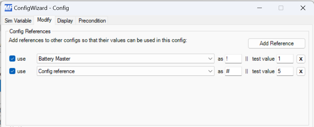
Config References allow us to access the value of an output config to be used in another input or output config. The following options are available:
- use - when enabled, the config reference will be available for this config
- name - the name of the reference based on its "description"-text
- as - define the placeholder which will be substituted
- test value - define the test value that shall be used when using the "test"-button. This can be any number or text.
Tip
-
The value of a config reference is linked to a placeholder character. This character link is only valid inside the input or output config where the Config Reference is made. In other words, the same placeholder character can be used to reference different independent values, in separate Config Reference definitions. There is no conflict.
-
This character can be any ASCII character. Care must be taken when selecting this character which cannot be used as part of the formula in which the config reference is referenced.
-
Predefined placeholders are
-
$- the current value of the config -
@- analog input value
For example: In a simple formula such as
if($=0,1,0)$ is the placeholder for the current value of the config, but it should be clear that although it is allowed, you CANNOT use any of the other characters in the formula (likei,f, or=) as placeholders, as doing it will destroy the formula when the placeholders are substituted by their respective values. -
Modifiers are used to change the value or appearance of the value received by an output config. You can think of modifiers as a chain where each modifier is a link. Each output from one modifier is passed to the next modifier as input in the chain. If convenient, the a given modifier may be used more than once in the chain.
There are currently six modifiers available:
- Transform
- Compare
- Interpolation
- Blink
- Padding
- Substring
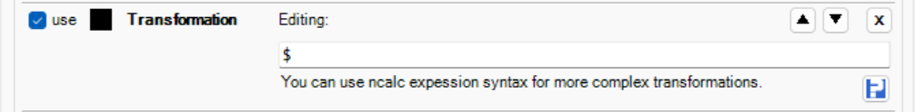
The Transformation modifier allows the use of an expression or formula (following ncalc syntax) to change the value of an output config. This expression may contain constants, placeholder characters, math or logical operators ( + - % & ) and ncalc functions (if, Min, Max, Round). This modifier is capable of handling string values.
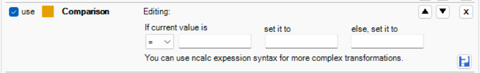
The Compare modifier allows to define simple Comparison rules. By this you can change the value before using it for output. This is quite useful for a broad number of FSUIPC offset values. It can handle string values. Example:** The indication of the Flaps Position - the output that drives the LED shall be 1 of the FSUIPC value is exactly 4096. In any other case it shall be 0 (off).
Hint:**You can only define one comparison rule. It is not possible to define e.g. a lower and upper limit at the same time. **You must use the powerful feature of "Preconditions" for this. With Preconditions you can combine an unlimited number of such conditions.
Tip
The following possibilities are available for the fields "set it to" and "else set it to":
- You can leave the field empty to use the currently provided value.
- You can also use
$to reference the currently provided number. - If you want to blank a 7-segment display module, you can use "SPACES"
- You can use characters as values for 7-segment displays, e.g. dashes
"---" - You can have complex calculations by using the supported expression engine syntax
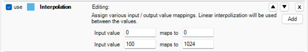
Create a conversion function between the input and output ranges, by defining two or more points. Mobiflight will linearly interpolate any point in the output range given a value in the input range. Non-linear relationships can be approximated by using multiple points of reference.
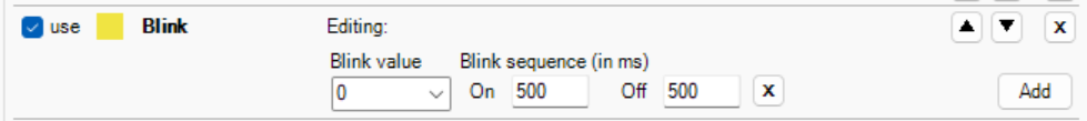
Intended for use with LED outputs, the Blink modifier will generate a repeating timed sequence of ON and OFF values following the time parameters defined as a Blink sequence. More complicated blink sequences can be created by adding two or more sequences together.

Intended for output formatting, the padding modifier will pad the specified character, to the right or left, to fill the number of characters in the specified field.

This modifier will extract the specified characters (start and end position) from the input string.
The Display-Tab allows you to define how the current value is displayed. You specify whether a LED is used or a LED 7 Segment Module or any other supported output type. Every output device and type has their own additional settings.
In the lower part of the tab page you can use the test mode function to verify that your display configuration makes sense. It triggers the same test function as if you run the Test Mode from the Main Window.
-
Display Type - You can define the following options
- Choose - Between "Output Device" and "Input Action"
Use one of your connected devices from your selected module to display the current value. Every device has their specific configuration. See more information about output device types and their options.
Options are:
- Module - The connected module that has the device that you would like to use
- Use type of - Select the type of device.
You can also trigger an Input Action if your current value changes. This can be either an input action based of
- Button-type - OnPress is executed when current value is "1", OnRelease is executed when current value is "0"
- Analog input - is executed on every value change. You can reference the current value by "@" in the value field (see hint below field).

You can define preconditions which have to be fulfilled so that your configuration is evaluated further. With this, more possibilities come up, like z.B. Multi-Radio-Instrumente, that depending on a switch' position show different readings. This allows to display e.g COM1, COM2, NAV1, NAV2 oder ADF on a common display. You can define an unlimited number of precondition items and combine them logically with "AND" or "OR".
In the upper part of the tab panel you see a list of currently defined preconditions. By right clicking on the list you access the context menu. There you have access to:
- Add precondition
- Remove precondition
- Select the logic Operator,which can be"AND" or "OR" - however there is no further grouping possible, the preconditions are evaluated sequentially.
You can also adtivate and deactivate a precondition. Active preconditions are marked with a "tick"
When you select a precondition from the list, you can specify the details of the precondition. Use type of ** - Defines the type of precondition
-
Config- You can use the value of another config entry. You can hereby use FSUIPC values from your Flight Simulator as precondition.
-
Choose config - You select the desired config entry from the drop down list
-
If current value is - You select the comparison operator and can define a value.
Hint: The comparison is always performed with the transformed value, the one that you see in the Output Value Column. Hence it is not using the raw value from the FSUIPC Offset. It is also possible to use the expression engine syntax here, where the current value is represented by "$".
-
-
Variable- You can access the value of any MobiFlight variable defined in output or input configs.
-
Choose variable - You select the desired variable from the drop down list
-
If current value is - You select the comparison operator and can define a value.
Hint: It is also possible to use the epxession engine syntax here, where the current value is represented by "$".
-
-
Pin (only for Arcaze)- the state of a pin, e.g. switch.
- Module- The Arcaze-Modul which shall be used
- Pin- The Pin which is used for evaluation
- If current state is - the value for a successful comparison: On or Off
Changes automatically are applied and saved to your config when closing the Wizard with "OK".
The Input-Config-Wizard let's you to edit your configuration items for your input devices in a user friendly and convenient way by distributing different aspects of the configuration over different tabs.
This dialogue only is available for MobiFlight Devices. Arcaze users define the input functions with the Arcaze Config Tool.
You can open the Input Config Wizard with the following actions:
- Click on "..."-Button in "Inputs"-configuration list on the Inputs-Tab
- Double click on a configuration item (row) on any cell other than "Description"
- Use space bar when the focus is set on "..."-Button - e.g. after using the tab-key.
You can define preconditions which have to be fulfilled so that your configuration is evaluated further. With this, more possibilities come up, like z.B. Multi-Radio-Instrumente, that depending on a switch' position let's you control different instruments with the same rotary switch or encoder. This allows to control e.g COM1, COM2, NAV1, NAV2 oder ADF with a common input device. In combination with the preconditions for outputs you have nice possiblities.
The precondition panel offers the same option as the panel of the Config Wizard for Outputs.
See this section for further details
On the Input-Tab you configure the actions that shall happen when using a defined input device.
First you select the desired device by choosing the MobiFlight Board (module) and the configured input device** from the respective drop down box.
Depending on the type you will see different Input settings options.
A button offers four separate action options or events.

- On Press - Is evaluated the moment the button is pressed
- On Release - Is evaluated when the button is released, if the press time was less than the specified Long Release time
- On Hold - NEW FEATURE Is evaluated when the button is held for longer than the specified time. Repeating event while hold is also possible.
- On Long Release - NEW FEATURE Is evaluated when the button is release, if the press time was longer than the specified Long Release time
- Hint: Note that both On Press and On Hold can be evaluated, if specified, but only either On Release or On Long Release will be evaluated depending on how long the button was pressed.
- Most momentary buttons will only use On Press
- Most latching switches will use On Press and On Release
Summary of the button action logic
- OnPress is always executed
- OnHold is always executed after configured Delay
- OnHold Repeat is always executed after first Delay and then repeatedly on RepeatDeley
- OnRelease is always executed if OnLongRelease is not configured
- If OnLongRelease is configured either OnRelease or OnLongRelease is executed depending on the Delay configured in OnLongRelease
An encoder offers four options or say events.

- On Left - Is evaluated whenever the encoder is turned left, but slowly
- On Left (Fast)- Is evaluated whenever the encoder is turned left, but quicker
- On Right - Is evaluated whenever the encoder is turned right, but slowly
- On Right (Fast)- Is evaluated whenever the encoder is turned right, but quicker
You don't have to assign for every event individual actions but you can.
Once you have selected your input device you can specify a action type for one of it's events (see above for the different device types and there events).