CSSE4011 Project Overview - MilindianaJone/CSSE4011-Uranus-Violet GitHub Wiki
Welcome to the CSSE4011-Uranus-Violet wiki!
Project and Scenario Description
Chosen Project: Copper 2 - Transmit camera image via Infrared (IR) link
Project Description: A serial camera connected to a nRF52DK board will be used to provide an image. This image will be transmitted via an IR Transmitter to an IR Receiver connected to a M5Core2 (using Zephyr). A suitable protocol for transmitting information over IR will be designed. Transmission will be attempted at a separation distance of 5m or more.
The following image is a hardware block diagram showing the flow of data through various hardware and their connections.

Software Overview
Below are flowcharts for the three different platforms which require programming, the PC GUI, nRF52DK board and M5Core. For all flowcharts, Y represents yes and N represents no. The ir_transmit_init() initialises both the IR transmitter and UART for nRF52DK, and ir_receive_init() initialises both the IR receiver and M5 Core device.

![]()

Team Member List and Roles
Yangyang Li and Milind Bordia
Yangyang is responsible for programming the M5Core2 using Zephyr. He is also responsible for ensuring that the image can be received at the 5m distance. He will also be responsible for making the GUI from the PC to the nRF52DK board. He has experience with the M5 Core and making a python GUI from previous pracs.
Milind is responsible for programming the nRF52DK board. He will ensure that the board can take an image from the serial camera and that the IR transmitter can successfully transmit the processed data. He will also work on the password protection between the transmitter and receiver. He has experience with the nRF52DK board from previous pracs.
They will both work together to establish a communication protocol which will be implemented on both boards. This protocol will include error checking and will be decided as the project progresses
Key Performance Indicators
- Transmission Success Rate: Measures the percentage of successful data transmission from the nRF52DK to the M5Core2. This KPI assesses the reliability of the communication protocol and the effectiveness of the hardware setup in achieving successful data transmission.
- Transmission Distance: Measures the maximum distance from which the image can be transmitted successfully (~90% accuracy). This KPI assesses the practical range of the transmitter and receiver system and its ability to maintain reliable transmission over distance.
- Transmission Time: Measures the time taken to complete the transmission of a single image from the nRF52DK to the M5Core2. This KPI assesses the efficiency of the communication protocol and how viable/practical the transmission method is.
- Protocol Overhead: Measures the amount of additional data transmitted along with the image data such as hamming bits or parity bits. This KPI assesses the efficiency of the communication protocol and the effect of additional data.
- Image Quality: Measures the dimensions of the image sent and also the bits/pixel. This KPI assesses the final quality of the image and directly reflects what the user will see.
System Integration
Sensors:
Serial Camera - The camera is connected to the nRF52DK board via a serial line. The camera will transmit raw image information using UART and will be connected via jumper cables. The capturing of images will be controlled via a PC GUI.
IR transmitter (technically not a sensor) - The transmitter is connected to the nRF52DK board. The board will communicate to the transmitter with UART and will be connected via jumper cables. The nRF52DK will provide data encrypted with a hamming code. This will increase the robustness of the image transmission as bit errors can be detected and rectified on the receiver end.
IR receiver - The receiver will be connected to the GPIO ports of the M5Core2. It will communicate to the M5Core2 via UART. The encrypted data provided by the IR receiver will be decrypted by code on the M5Core2. This processed data can then be used to display the image.
Wireless Network Communications
With one transmitter and one receiver in your setup, the network topology would be a simple point-to-point topology. This means that communication occurs directly between the transmitter and the receiver.
In this topology:
- The transmitter is responsible for sending data.
- The receiver is responsible for receiving data.
IR Transmission Protocols
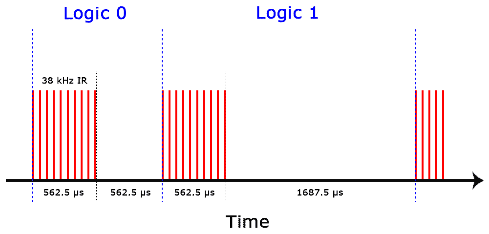
The pattern in which the modulated IR signal is converted to binary is defined by a transmission protocol. There are many IR transmission protocols. The NEC protocol is also the most common type in Arduino projects.
Logical ‘1’ starts with a 562.5 µs long HIGH pulse of 38 kHz IR followed by a 1,687.5 µs long LOW pulse. Logical ‘0’ is transmitted with a 562.5 µs long HIGH pulse followed by a 562.5 µs long LOW pulse:
The IR transmitter will need to send unique codes dependent on the image sent for the receiver to decode. These codes will be in the form of hexadecimal values representing the colour of each pixel in the provided image. Each image has dimensions 320x240, which means a total of 320x240x3=230,400 bytes per image need to be transmitted.

MQTT
MQTT has been chosen to communicate between the base node and the receiver image node. This is to add a layer of security to the device, by making it password protected. The messages will be in a JSON format.
MQTT Host (Broker): csse4011-iot.zones.eait.uq.edu.au
The base node will send a username and encrypted password, in the format of {"username": "studentID", "password": "8sh3jbak3"}. The receiver node will decrypt the password for the username and return to the base node if the user was successful in joining: {"username": "studentID", "success": "yes"}.
UART Transmission Protocol
The UART transmission between the PC GUI and nRF52DK board will be similar to previous practicals. However, the type provided will be of 0x03, which is specific to an image. This means bytes to describe the length aren't required.
| Preamble | Type | Data Field |
|---|---|---|
| 8 bits | 8 bits | 230,400 bytes |
| 0xAA | 0x03 - Request | Data bytes of Image |
Algorithms
- NEC IR algorithm for sending and receiving
- Special message detection for signaling new-lines
DIKW Pyramid
The IR image transmission system can be useful when data must be transferred wirelessly, at a low latency and securely. This system may be used as part of a larger surveillance system. Using IR transmitters and receivers to communicate an image can provide the additional security of ensuring that the data is not exposed to outsiders. Unlike WiFi or Bluetooth, the data is only available in direct line of sight and cannot pass through walls.
The following DIKW pyramid outlines the possible contributions of the IR image transmission system to surveillance applications:
Equipment
- 1 nRF52DK board
- 1 M5Core2
- 1 Serial Camera
- 1 IR transmitter
- 1 IR receiver
- Jumper Cables
IR Equipment examples here.
Progress
A simple GUI has been developed which can control the capturing of an image. The GUI can print the raw image data.
16/05: The IR transmitter was tested with the provided NRF board. The PWM directly from the nRF52 board worked correctly, as the voltage oscillated between 0 and 3V, with a frequency of 38kHz as required for the IR to function. However, the IR requires a minimum of 3.3V, which the GPIO from the nRF does not provide, and so we used the MOSFET as mentioned in Edstem post #227. However, this MOSFET was unable to drive the PWM signal effectively, as it hovers around 4.5V with no clear PWM. We deduced that the signal must be too fast for the MOSFET to effectively drive the signal. We've tried multiple different options, including different battery sources and different MOSFETs but the results are always the same.
PWM signal sent from NRF:

PWM signal from MOSFET:

18/05: The decision was made to swap the base node to an Arduino Uno. This is because the Uno can power the IR, as it can provide a PWM output at 5v which the IR transmitter can actually transmit. We are using an Arduino only for the purpose of image capture and sending. We are still using Zephyr to program the M5Core module to receive the image.
19/05: Image transmission is successful with us being able to recognise the image transmitted over IR. We have deduced that the environment for the transmission is critical to the accuracy of the received data. The exchange must happen indoors and away from any IR noise such as the sun. MQTT has also been implemented. The receiver node (M5core2) will send a message via MQTT which the sending node (arduino) will pick up. This message is a confirmation that the image has been successfully received.
![]()
References
Circuit Basics. How to set up an IR Remote and Receiver on an Arduino. Retrieved from https://www.circuitbasics.com/arduino-ir-remote-receiver-tutorial/#:~:text=The%20receiver%20diode%20detects%20all,sending%20it%20to%20a%20microcontroller.