Your first own VGA Board - Megatokio/kilipili GitHub Wiki
Here i want to provide a step-by-step introduction to your first own VGA board.
- Buy or build
- How many colors
- Assign GPIOs to VGA and other peripherals
- Calculate resistor values for VGA
- Construction tips
- Example board - the KiBoard
- The 'board' description file
Buy a finished board
The Raspberry foundation has published a board design which has been manufactured and is sold by some dealers, most notably by Pimoroni. This board offers RGB555 video and 2 methods of audio for experimenting, but the SD card is attached in 4 bit parallel mode which i don't plan to implement for lib kilipili (maybe you want?) and it shares pins with the serial port. Overall they wanted just to much for the available pins. But if you don't want to build any own hardware this is the obvious place to start.
How many colors
The Raspi Pico has no analog outputs. The analog signal for VGA must be mixed from multiple GPIO pins with resistors of different values. The more shades you want the more pins you need. The Raspberry reference board uses RGB555, which means 5 bit per color or 2^5 = 32 shades per color component which is more or less the maximum you can achieve. (RGB565 is the actual maximum). But uses a lot of GPIO pins and requires higher precision resistors for the resistor network to achieve a smooth gradient. On the other side RGB111 with just one pin per color component is the bare minimum. Between these two extrema you can decide.
If you plan to create an emulator of some old hardware then this obviously determins the minimum for your board. Besides that more colors look better but are more work. memory usage increases when you go above 8 bits but mostly only for true color images. I recommend to consider one of the following:
- RGB111 the bare minimum
- RGB222 already 64 colors
- RGB332 uses ram most efficient
- RGB444 already very good looking images
- RGB555 high end solution
Assign GPIOs to VGA and other peripherals
Next decide on which peripherals you also need. Consider an SD card, a serial port, one or two audio outputs and maybe one or two I²C for WII style game controllers. The USB host port is almost for free, you only need an USB-to-go adapter to attach USB controllers and keyboard. Now count the pins and it surely must be less than 26 because that is the number of GPIOs available on a standard Pico board.
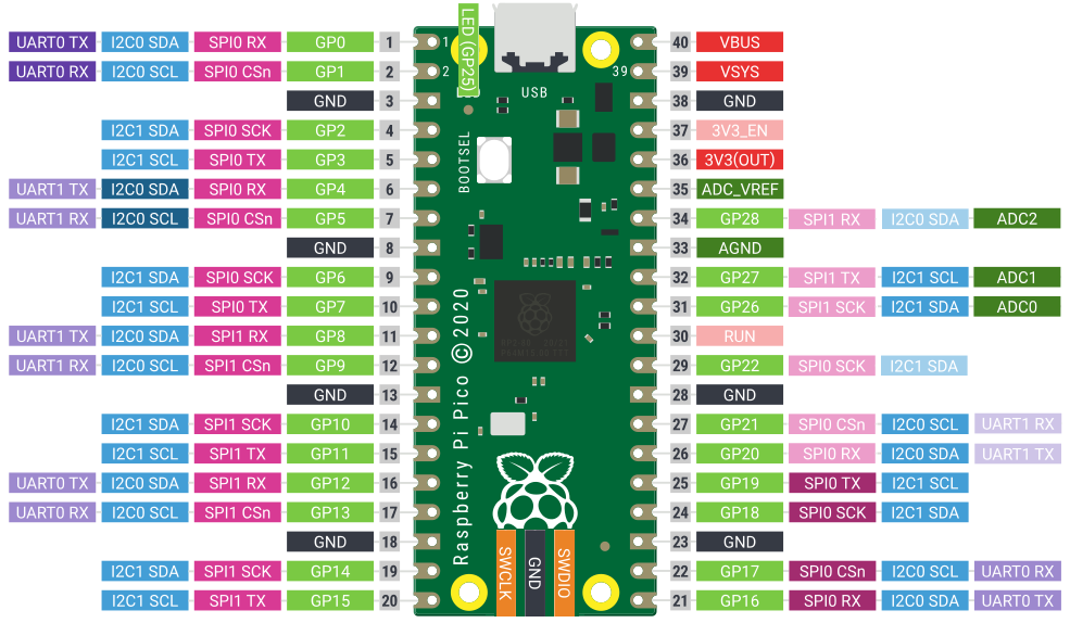
For VGA you need the color pins plus 2 additional pins for Hsync and Vsync (and 2 more if you want to attach a LCD panel with CLK and D_en), for the SD card you need one SPI block with 4 pins and I²C and serial are 2 pins each. Audio depends on the method to use, PWM and delta-sigma audio need 1 pin per channel while I²S needs 3. The color bits of VGA must come in consecutive order, or, at least they must all fall into the range of one byte (8 bit) or one halfword (16 bit), within that rule gaps are allowed.
Calculate resistor values for VGA
VGA color inputs have a resistor of 75Ω to ground and require a maximum (white) level 0f 0.7V. The GPIO outputs of the Pico switch between 0V and 3.3V, so we need (3.3V-0.7V)*75Ω/0.7 ~ 279Ω. This is the value for one resistor, so for RGB111 you can directly use a 279Ω resistor.
Multiple pins mixing into the same signal are more complicated. First they must be a binary ladder, 1:2:4:8 so that lower bits always contribute only half of the current as the higher bit. Then they all combined must result in 279Ω. This gives the following values:
- one bit: 279Ω
- two bits: 836Ω + 418Ω
- three bits: 1950Ω + 975Ω + 488Ω
- four bits: 4178Ω + 2089Ω + 1044Ω + 522Ω
- five bits: 8636Ω + 4318Ω + 2159Ω + 1079Ω + 540Ω
Of course these precise values are not available. So we go to the nearest values:
- one bit...: 270Ω
- two bits..: 820Ω + 820Ω/2
- three bits: 1kΩ*2 + 1kΩ + 1kΩ/2
- four bits : 3k9Ω + 1kΩ*2 + 1kΩ + 1kΩ/2
- five bits : 9k1Ω + 4k3Ω + 1k1Ω*2 + 1k1Ω + 1k1Ω/2
While the error from the total value results in a picture slightly too bright or to dark where 5% off is totally acceptable, the relative value should be close to 1:2:4:8.. This is most easily accomplished by starting with a 'base value' and putting two of the same value in series to get twice and two in parallel to get half of that value. If all these resistors com from the same lot then additional chances are that their values are even more similar than just two random resistors.
How precise should the resistors be?
The error for the lowest bit (the highest resistor) should not exceed 10%. 20% is the maximum acceptable error or you can clearly see it later in the image. Each next step must have at most half of that error. So for example RGB444 we need resistor values with 10, 5, 2.5 and 1.25% precision. If we use the trick with soldering two in parallel and another two in series we can easily get away with 2% values for the highest 3 bits. For the lowest bit, which should be 4kΩ in this case, we use the available 3k9Ω from the E24 series with 5% precision, but 10% will also be ok. For best result measure the resistors with a multimeter and pick the best.
I also suggest to put a small series resistor in the hsync and vsync lines, e.g. 33Ω.
Construction tips
If you have not yet soldered a header to your Pico board then you can leave out the pins for the color pins and solder resistors into these pins directly.
The easiest way to get a VGA connector for your board is to pick a random VGA connection cable and cut it in half! Then you have even two of them, one for your board and one for your friends. :-)
Connect Vbus and Vsys (pin 40 and pin 39) if you want to use the USB in host mode to attach a keyboard or game controller.
Solder a 100µF capacitor accross the power supply of the SD card connector. The Pico's voltage regulator isn't that good.
Example board - the KiBoard
As an example here is my personal board.
It has RGB444 VGA output, using 14 pins of the available 26 GPIO pins in total. I recommend to use the left side of the board for VGA.
Then there is a serial-to-USB adapter connected, which can also power the board if the USB is disconnected from my desktop computer to attach a keyboard in host mode.
A SD card adapter is connected to GPIO 16 to 19. The SD card is accessed in SPI serial mode. I recommend this position for the SD card.
Two pins are used for audio output which happen to be (for some purpose) two of the ADC pins. My plan is to use delta-sigma output.
And i want to experiment a little with Wii controls and therefore there are two I²C ports.
    SDA I²C --- 0          Vbus --+
    SCL I²C --- 1          Vsys --+
              GND          GND
R0 VGA --4kΩ -- 2          x
R1 VGA --2kΩ -- 3          3V3 out
R2 VGA --1kΩ -- 4          x
R3 VGA --500 -- 5          28 --> Audio
              GND          GND
G0 VGA --4kΩ -- 6          27 --- I²C SCL
G1 VGA --2kΩ -- 7          26 --> Audio
G2 VGA --1kΩ -- 8          reset
G3 VGA --500 -- 9          22 --- I²C SDA
              GND          GND
B0 VGA --4kΩ-- 10          21 <-- serial port
B1 VGA --2kΩ-- 11          20 --> serial port
B2 VGA --1kΩ-- 12          19 --- SDCard SPI0
B3 VGA --500-- 13          18 --- SDCard SPI0
              GND          GND
  hsync VGA -- 14          17 --- SDCard SPI0
  vsync VGA -- 15          16 --- SDCard SPI0
The 'board' description file
Each project must define a board description file with some board-specific definitions. The default which is used by the SDK is just for the naked Pico board with some assumptions where some peripherals may be located by default. If you have already tampered with the Pimoroni board you know that you can also set 'vgaboard' to provide a board description for your board. These descriptions are located in .../pico-sdk/src/boards/include/boards/. (why not even deeper?) You can put your board description file here too but this separates the board description from your project. kilipili provides a folder for additional board descriptions in kilipili/boards. This folder is added in the CMakeLists.txt. Here you can put your board description.
Then you run cmake with -DPICO_BOARD=your_board_name or you set this cmake variable in your IDE ... you should know how and where.
The kiboard board description file
A short walk-through through the board description file for the kiboard example board. The file itself can be found in kilipili/boards/kiboard.h.
// Serial
// this is conencted to GPIO 20/21 which is the UART block #1. (see Pico board image above)
#define PICO_DEFAULT_UART 1
#define PICO_DEFAULT_UART_TX_PIN 20
#define PICO_DEFAULT_UART_RX_PIN 21

// Video
// define the lowest GPIO used for color bits
// define the total number of color bits incl. possible gaps (used to determine the PIO program)
// define the GPIO for hsync (vsync is at hsync+1)
#define VIDEO_COLOR_PIN_BASE  2
#define VIDEO_COLOR_PIN_COUNT 12
#define VIDEO_SYNC_PIN_BASE   14

// define the offset from VIDEO_COLOR_PIN_BASE for each color
// and the number of bits for each color.
// they must not exceed VIDEO_COLOR_PIN_COUNT.
// the low bits must be the lower GPIO pins.
#define VIDEO_PIXEL_RSHIFT 0
#define VIDEO_PIXEL_GSHIFT 4
#define VIDEO_PIXEL_BSHIFT 8
#define VIDEO_PIXEL_RCOUNT 4
#define VIDEO_PIXEL_GCOUNT 4
#define VIDEO_PIXEL_BCOUNT 4

// Audio
#define PICO_AUDIO_SIGMA_DELTA
#define PICO_AUDIO_LEFT_PIN      28
#define PICO_AUDIO_RIGHT_PIN     26

// other Audio options:
// #define PICO_AUDIO_NONE
// #define PICO_AUDIO_BUZZER
// #define PICO_AUDIO_I2S
// #define PICO_AUDIO_PWM

// SDCard
// define the GPIO pins used for the SD card. GPIO 16 to 19 are for the SPI block #0. See Pico board above.
// RX, TX and CLK must use the same SPI block, CSn may be any pin, but best use the defaulrt pin.
#define PICO_DEFAULT_SPI 0
#define PICO_DEFAULT_SPI_RX_PIN  16
#define PICO_DEFAULT_SPI_CSN_PIN 17
#define PICO_DEFAULT_SPI_SCK_PIN 18
#define PICO_DEFAULT_SPI_TX_PIN  19
#define PICO_DEFAULT_SPI_CLOCK	 10000000

// I2C
// I want to tinker with Wii devices so i use 2 I²C ports:
#define PICO_DEFAULT_I2C 1
#define PICO_DEFAULT_I2C_SDA_PIN 22
#define PICO_DEFAULT_I2C_SCL_PIN 27

#define PICO_SECOND_I2C 0
#define PICO_SECOND_I2C_SDA_PIN 0
#define PICO_SECOND_I2C_SCL_PIN 1

// pull in Pico defaults
#include "boards/pico.h"