GUI Application Documentation - MacCurdyLab/OpenVCAD-Public GitHub Wiki
GUI Application
OpenVCAD can be built as lightweight IDE that includes a text editor, 3D rendering preview, multi-material compiler, and file exporter. The application can be used to edit and preview what .VCAD files. This documentation provides an overview and basic usage of the GUI.
UI Overview
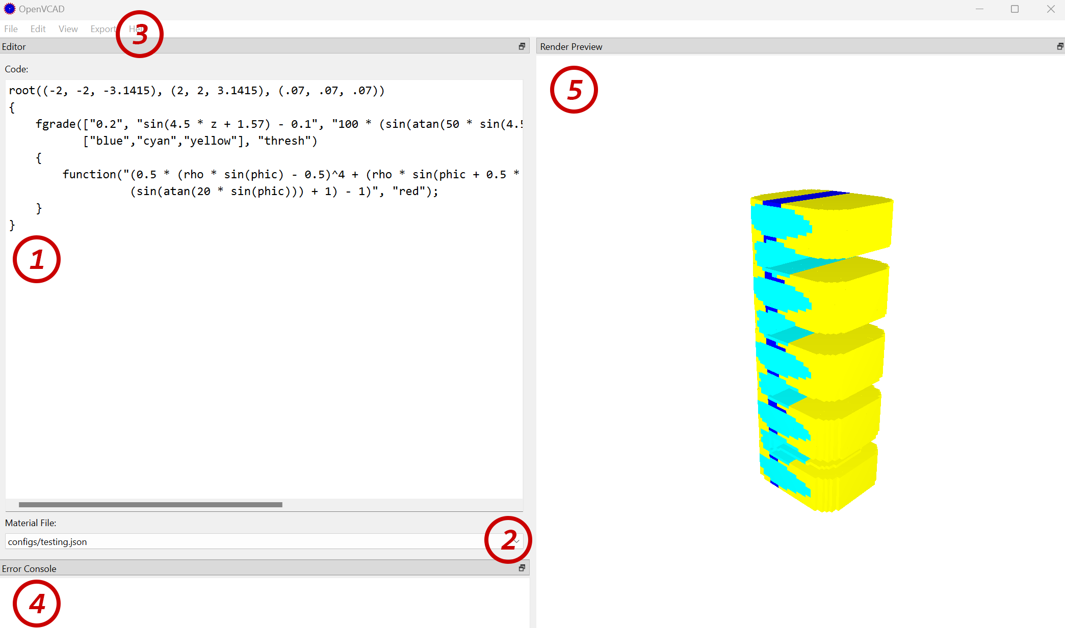 The OpenVCAD IDE is comprised of 3 primary panels: a code editor, a render preview, and an error console. Panels can be undocked and placed on separate screens, resized and hidden. However, all panel sates are reset when the application is relaunched. The common workflow for designing, compiling, and preview a part is as follows.
See numbers on image above for corresponding actions
- Use the Code Editor window to write a
.VCADscript for a particular design - Select a material configuration file that contains matching names for the material you used in your deisgn. See Material Definition Files for more info on the file structure.
Note: You can use
File->Open Material Configs Directoryto add/ edit material files.
- In the menu-bar click on
View->Render Voxelsto compile and view the file. - If there is an error compiling your design, an error message will appear in the Error Console.
- After a few moments, the Render Preview will update with your design.
Note: Very large design or sample volume will take a long time to process. It is recommended that you use a larger voxel size when iterating on your design in the IDE. This can be configured in the root node.
Render a Design
A design can be previewed in the rendering panel using two modes:
Voxel Preview
The voxel preview renders the design as a set of 3D-voxels. The design is compiled into voxel space by sampling across a range and voxel size specified in the root node. When the number of voxels in the sample space grows large (as a result of a small voxel size, or a large volume), then the render will take a long time to process. It is recommended to keep these values small for rendering. You can render with this mode using: View->Render Voxels or Ctrl + R.
Iso-surface Preview
Another method to visualize the design is as a iso-surface. This mode first compiles the design into voxels. Then the voxel grid is converted into a triangulated surface mesh using the marching cubes algorithm. This mode requires a larger upfront investment in time to initially render, however yields much better frame rates with design comprised of many voxels. You can render with this mode using: View->Render Iso Surface
Ray-traced Preview
This is the best way to visualize objects with transparency. This method uses a sparse-voxel ray-tracer to draw objects in real-time. It also provides transparency, animation, and lighting controls. Depending on your GPU, you can select from various real-time performance profiles. This method is faster than the voxel preview.
NOTE: The ray-traced preview requires an NVIDIA CUDA capable GPU.
Export a Design
Once you have completed your design, you will need to export it to a format accepted by multi-material 3D-printers. OpenVCAD supports two primary method for exporting design.
PNG/ Bitmap Stacks
The most common form are bitmap stacks. These are layer-based slices of the design saved as multiple image files. OpenVCAD supports exporting PNG stacks using the Export Dialog. This tool allows a user to specify the director path that they will export their image files to. A file name pattern in the form NAME_XX.png where XX is automatically replaced by the layer numbered slice. An image format that the .PNG fill will be saved as.
Note: If you pick an image format that does not support an alpha channel, then you will need to change the
"void"color to something other than clear. See material file configuration.
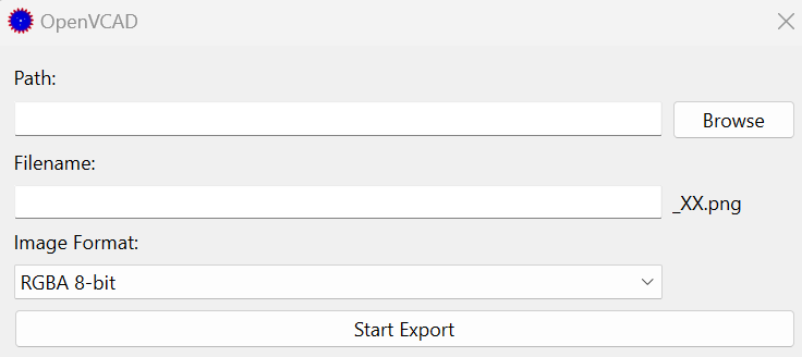 The PNG Stack export dialog can be opened using
 Export->PNG Stack in the menubar.
OpenVDB Grids
OpenVCAD design can also be compiled into OpenVDB grids using Export->VDB File. This will create a single file that contains two 3D-grids: 1. a scalar field level-set that represents the geometry of the iso-surface, and 2. a grid that contains the material values for the geometry.
Abaqus INP Mesh
Please contact Charles Wade at [email protected] for more information.