TS1 Operations Guide - MOARdV/AvionicsSystems GitHub Wiki
(This page is in-progress. I will update it as I complete MFD pages that need explanations)
The MAS TS1 MFD is a touch-enabled multi-function display. The goal of the TS1 is to put as much of the management and information functionality into a single MFD, allowing it to be the primary interface with the vessel.
The TS1 is organized into two sets of pages - DISPLAY and CONFIG. A DISPLAY page shows information, possibly with some control capability. A CONFIG page allows configuring the DISPLAY page, as well as providing controls related to the DISPLAY. For instance, the FLIGHT DISPLAY page provides a conventional basic-T arrangement of instruments useful for atmospheric flight. The FLIGHT CONFIG page allows the pilot to select different ways of displaying that information. For example, if the pilot is commanding a space plane that is starting its orbital insertion, the pilot may swap the artificial horizon instrument (AHI) for a navball (FDAI, or Flight Director/Attitude Indicator).
Each mode of the MFD has a DISPLAY page and a corresponding CONFIG page. All DISPLAY pages have a touch-button on the bottom to switch to the corresponding CONFIG page, and CONFIG pages have DISPLAY buttons in the same location.
DISPLAY/CONFIG SELECT
TODO: screen shot, and a list of the pages and summaries of their use.
FLIGHT
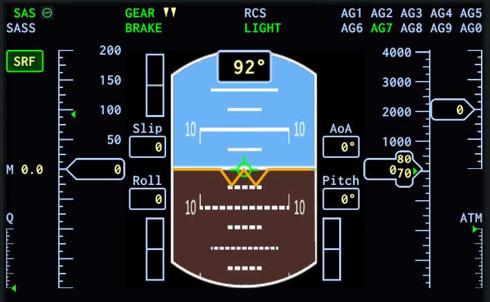
The FLIGHT DISPLAY page provides instrumentation useful for flying aircraft and spaceplanes. It is organized as a basic-T, with attitude display top-center, speed information on the left, altitude information on the right, and heading in the bottom-center. The CONFIG page allows the pilot to swap various instruments depending on flight parameters.
The upper instrument cluster is portrayed in the image above. It is configured with the Ladder option for both speed and altitude, and the AHI for the attitude display.
Announcers

At the top of the page (and every page of the MFD) are the announcers. These display the settings of various action groups (including Brakes, Gear, Lights, RCS, and SAS). In addition, the MechJeb SASS setting is displayed.
Text appears pale blue if the corresponding action group is 'off', and it appears green if the action group is 'on'. This on/off status does not does not reflect the state of any actions attached to the action group. For instance, if AG1 extends an antenna, and AG2 retracts it, the AG1 and AG2 announcers do not tell you whether the antenna is extended or not - all it tells you is if the action group has been toggled an odd number of times (green) or an even number of times (pale blue). These announcers are more useful when the actions that are attached to them toggle something.
Some announcers display extra information:
- The SAS announcer includes an icon displaying what mode SAS is currently in.
- The MechJeb SASS announcer displays the mode that SASS is in when enabled (feature not implemented).
- The GEAR announcer displays arrows indicating whether retractable landing gear is up or down, or currently extending or retracting.
- The RCS announcer displays icons when RCS is enabled and RCS is firing.
Speed

The speed ladder displays current vessel speed. This speed is always in meters per second (m/s). The relative frame of the speed is provided by the announcer/button in the upper-left corner of the speed cluster (labeled A, above).
- A - Speed Mode Indicator. This will display SRF (surface), OBT (orbit), or TGT (target). Tapping this announcer will select the next mode.
- B - Speed Ladder. The speed is displayed numerically in the window next to the letter 'B'. The ladder will scroll in response to the current speed.
- C - Terminal Velocity Indicator. The green arrow displays the current terminal velocity for the vessel. In this screen shot, it is approximately 90 m/s.
- D - Dynamic Pressure Indicator. Visible only in an atmosphere. The dynamic pressure, Q, can range from 0kPa (bottom of the scale) to 40kPa (top of the scale).
- E - Mach Number. Visible only in an atmosphere. Reports the current Mach number of the aircraft based on current air speed and atmospheric conditions.
Altitude

The altitude ladder displays current vessel altitude and vertical speed. Altitude is always reported in meters (m).
- A - Current Altitude. The aircraft altitude above the datum (mean sea level on planets with an ocean) is reported in meters.
- B - Radar Altitude + Altitude Trend. The green arrow indicates the altitude above ground level. A magenta bar (not visible in this screen shot) shows the projected altitude of the aircraft ten seconds in the future based on the current vertical speed.
- C - Vertical Speed. The vertical speed of the aircraft in meters per second (m/s) is displayed in the numeric window. This window slides relative to the associated ladder to provide a relative rate.
- D - Atmospheric Pressure. Visible only in an atmosphere. This gauge reports the current static pressure of the outside environment in atmospheres (Kerbin sea level = 1). The top of the gauge indicates 1ATM, the bottom indicates 0ATM.