Operations Manual Mk1 - FirstPersonKSP/AvionicsSystems GitHub Wiki
The Mk1 Operations Manual provides an introduction to the Mk1 MAS-enabled Command Pod. In addition, it introduces a number of concepts common to MAS-enabled IVAs.
The Mark 1 Command Pod is a basic sub-orbital or briefly-orbital command pod used early in a space program. As such, it has minimal instrumentation. There is no interface with MechJeb (or MAS) autopilots, since this IVA is intended to be relatively primitive.
Left Instrument Panel

The left control panel consists of a 3 x 5 array of Flag Indicators, a few switches, and a rheostat.
A Flag Indicator is used to indicate when a particular status indicator is active, similar to a Lamp Indicator. Often, the Flag Indicator (FI) will display a colored rectangle (often, green with black stripes for nominal status, or yellow or red with black stripes for out-of-spec status). In the screen shot above, all FI are 'off', reporting that none of the indicators are active. A FI is a status indicator only - it can not be clicked to change status.
In the Mk1 CP, the left two columns of FIs indicate which Action Groups are active. Each is labeled with the caption corresponding to the Action Group (eg, 'AG1' for Action Group 1). AG0 applies to Action Group 10. The right columns reports which other stock groups are active - Brake, Gear, Light, RCS, and SAS.
Below the FI is a row of three Toggle Switches. The left two, BRAKES and GEAR, are probably not useful for a suborbital Mk1 command pod. The last switch, EXT. LIGHTS, toggles the Lights action group (which will toggle the command pod window lights in external views, by default).
Below these toggle switches is one more toggle switch and a rheostat knob.
The toggle switch is used to arm the pods parachute. As long as defaults have not been changed, once it is armed, the parachute will deploy automatically once it is safe to do so.
The rheostat is a knob that can be adjusted to vary inputs. In this case, the knob controls instrument lights. Pressing and holding on the right side of the knob will increase backlight brightness. Pressing and holding on the left side will decrease it. As one of the first steps for pre-flight activity, adjust backlight brightness to an acceptable level.
Upper Instrument Panel

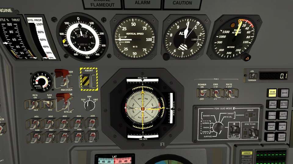
The top-most section of the instrument panel provides instruments related to flight conditions. Note that the instrument panel backlight has already been adjusted to full brightness. From left to right:
ENGINE gauge, showing current commanded throttle position and current actual thrust output.
STG. PROP. gauge, showing the remaining propellant for the current stage.
SPEED gauge, showing current vessel speed in m/s. This instrument can report in any of three modes: SURFACE (yellow S flag is visible on the left, like in this screen shot), TARGET RELATIVE (red R flag is visible on the left), and ORBIT (no flags). The outer ring and black arrow needle report meters/second, the inner ring and white needle report thousands of meters per second. This instrument goes out of limits at 9,000m/s.
VERTICAL SPEED gauge, showing vertical speed in m/s. This instrument goes out of range at +/-100m/s. It requires atmospheric pressure to function, and it returns to 0 in vacuum.
ALT gauge, showing altitude above sea level in meters as well as current static atmospheric pressure. The thin wire needle reports hundreds of meters, the narrow long needle reports thousands of meters, and the short wide needle reports tens of thousands of meters. This instrument requires atmospheric pressure to function.
RADAR ALTITUDE gauge, showing altitude above ground in meters. This instrument goes out of range at 1500 meters. In addition to the altitude needle, there is an orange chevron that can be adjusted using the knob in the corner of the instrument. This chevron indicates the altitude at which an audible warning and the orange warning lamp on the radar altimeter will activate. If the warning altitude is left at 0, no alarm will trigger.
Above the center of the gauges are the ENGINE FLAMEOUT warning panel, the master ALARM warning panel, and the master CAUTION warning panel. These illuminate when there is a fault that needs attention.
Main Instrument Panel

The main instrument panel contains controls and instrumentation vital for flight operations. From left to right, the panel consists of:
Left side, main panel
ACCEL gauge, reporting current vessel acceleration in g units.
RECOVER switch, to recover the vessel. Note that the red cover on this switch opens automatically when the vessel is no longer in flight.
ABORT switch, to trigger the abort sequence. This switch includes a safety cover to prevent accidental triggering of the abort sequence.
RCS switch, to activate RCS (when installed).
SAS switch, to activate SAS.
STAGE switch, to stage the vessel. This switch includes a safety cover to prevent accidental staging. Closing this cover also locks staging from the keyboard.
SPEED MODE selector, to select whether the SPEED gauge reports target-relative speed (TGT), surface speed (SRF), or orbital speed (OBT).
Action group switches AG1 through AG0 (action group 10). If the vessel uses AGMEMO naming, these switches will show the memo name instead of generic AG numbers.
Center, main panel
The center of the panel consists of the FDAI instrument. This instrument is critical to flight operations, since it provides vessel orientation, roll rates, and errors relative to selected headings. This instrument's operations are described in How to FDAI on the MOARdVPlus mod wiki.
Right side, main panel
The FDAI POWER, ERROR, and RATE switches, and the FDAI GUID MODE panel, are adjacent to the FDAI. Refer to How to FDAI on the MOARdVPlus mod wiki for details on how to operate this instrument.
To the right of the FDAI switches is the digital altimeter / radar altimeter. This is a cheat instrument, since it is available at all times, even in vacuum. Altitude is reported in km. The toggle switch switches between altitude above sea level (ASL) and radar altitude (TERRAIN).
Below the digital altimeter are the SAS mode buttons. SAS mode buttons have no effect until SAS is switched ON (SAS switch, left main panel).
To the right of the SAS mode buttons are the POWER gauge, showing remaining electrical power, and the MONOPROP gauge, showing available Monopropellant.
Lower Instrument Panel
The lower instrument panel consists of the Globus/IMP position indicator. This instrument can show the current position of the vessel, a target, or the projected landing site of the vessel. This position is reported visually by adjusting the position of the globe, as well as numerically by adjusting the position of the LAT (latitude) and LONG (longitude) strips.
The IMP power switch is used to activate the instrument. Adjacent to the IMP power switch is the IMP MODE selector knob. It consists of three settings: TGT (target position), VESSEL (current vessel position), and LANDING (projected landing position).
If the IMP is switched ON, and the IMP MODE selector is in an invalid position, the IMP illumination lamps switch off, and the globe returns to the (0, 0) off position.
To the right of the IMP is the DSKY orbital data computer. This instrument is fully described on the MOARdVPlus mod wiki under How to DSKY.
Pre-flight Checklist
- Adjust instrument panel backlight (INST. PANEL rheostat, left panel). Recommended setting during launch is maximum brightness.
- Enable external lights (EXT. LIGHTS switch, left panel to ON).
- Adjust radar altimeter warning altititude (RADAR ALTIMETER gauge, upper panel).
- Open the abort safety cover (ABORT switch, left main panel).
- Switch SAS to ON (SAS switch, left main panel).
- Activate any action groups appropriate to pre-flight and launch conditions (AG switches, left main panel).
- Switch FDAI to ON (FDAI POWER switch, right main panel).
- Adjust FDAI error (FDAI ERROR switch, right main panel).
- Switch FDAI mode to SURFACE PROGRADE (FDAI GUID MODE panel, right main panel) by checking the knob is set to SURFACE and the +/- switch is set to +.
- Switch IMP to ON (IMP POWER switch, lower panel).
- Verify IMP MODE is set to VESSEL (IMP MODE switch, lower panel).
Once you've completed these steps, the Mk1 is configured for launch. Throttle to 100% and click the STAGE switch. Once you're above 100m/s vertical speed and about 1000 meters up, start the pitch maneuver to a few degrees off vertical (I tend to pitch 15 degrees over with higher thrust-to-weight vessels). Once the error needles on the FDAI are close to zero, switch SAS to PROGRADE. You may then adjust throttle as needed to maintain the ascent path you're seeking.