Lab 2 Thermocouples - MAE221/Thermodynamics-Lab GitHub Wiki
- Become familiar with a temperature measurement sensor (Type T Thermocouple)
- Calibrate a Dial Thermometer
- Understand Signal Conditioning (Instrumentation Amplifier)
- Record and compare Thermocouple data vs Dial Thermometer readings using your Photon
One of the main motivations for teaching electronics and data acquisition in this lab is to help you understand the data acquisition and processing that will occur in the thermodynamics labs that will follow. The final link to this is sensors. This lab introduces thermocouples and signal conditioning. This lab will combine what you have learned in Lab 1 - using resistors in series and parallel networks to analyze the behavior of mechanical devices.
A thermocouple is a temperature measurement sensor consisting of two dissimilar metals joined together at one end (a junction) that produces a small thermoelectric voltage. A change in that voltage is interpreted as a change in temperature. The thermocouple is not a linear sensor, rather, it follows a polynomial relationship. It is a direct polynomial when converting from microvolts to degrees Celsius and an inverse polynomial converting degrees Celsius to microvolts.
There are many types of thermocouples such as J, K, T, and E to name a few. They all have different and sometimes overlapping temperature ranges. For the exercise that follows, we will be using a Type T thermocouple consisting of one copper wire and one copper-nickel alloy (constantan) wire.
Since any junction between dissimilar materials will create a voltage, care must be taken in attaching the thermocouple to the voltmeter to measure voltage. When each wire is attached to one of the voltmeter terminals, a new thermoelectric voltage is created. If the two wires attached to the terminals are of different materials, these voltages are different and depend on the temperature at the terminals. Since we now have three competing junctions, each with its own voltage, it is impossible to say what the voltage (and therefore temperature) is of the original thermocouple junction.
This situation can be remedied in one of two ways. One way is to use an electronic compensator which is designed to output a compensating voltage to cancel out the spurious terminal voltages. These circuits are used in commercial temperature transmitters. A simpler, though less convenient method, however, is to introduce yet another junction at a known temperature as is shown in Figure 1. Both leads to the terminals are now of the same material, so that the thermoelectric voltages created at the voltmeter terminals cancel. The voltmeter now reads the difference between the voltages of the two remaining junctions which we will call the active and reference junctions. If the reference junction is then held at a constant, known temperature, the temperature of the active junction can be determined. The most convenient temperature is 0°C, which is easily achieved using an ice bath. This technique is known as Cold Junction Compensation (CJC).
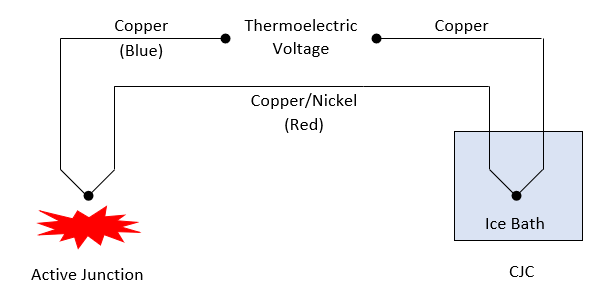
Figure 1: Thermocouple Setup
Your photon outputs +4.8 volts (single supply) on the pin labeled VIN. The AD623 requires a dual supply +/- 4.8 volts. We can construct a very simple circuit to do this using the ICL7660 and 2 capacitors.
Note: From now on we will be referring to the supply voltage as either 4.8 volts or 5 volts interchangeably

Figure 2: Dual Power Supply Circuit

Figure 3: AD623
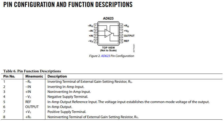
Figure 4: AD623 pinout diagram
Transfer function for the AD623. Where Vi is defined as Vin on the non-inverting terminal minus Vin on the inverting terminal.
Equation 1

Figure 5: Thermocouple Circuit
Figure 3 shows the inner workings of an amplifier. You don't have to worry too much about knowing how it works; modern amplifiers are pretty complex devices so we don't expect you to know how exactly it works. All amplifiers work by amplifying a signal using a complicated array of resistors, transistors, and diodes. The amplifiers that you are using for these experiments aren't exactly like the ones that you see in your cars or speaker systems; however, they share several similar properties by amplifying tiny voltages (in this case, the voltage from the thermocouple wire, in the case of speaker systems, by amplifying analog sound signals).
You have been given a four-feet long piece of thermocouple wire. Remove about 2 inches of the brown insulation from both ends of the wire. Do this by cutting down the middle of the insulation with a knife or other cutter, peel off the insulation, and cut it off. Be careful to only cut the brown insulation and not to cut the red or blue wire. Inside you will see a red and blue wire. Remove about 1⁄2 inch of insulation from both wires on both ends of the thermocouple wire. Then twist the bare red and blue wires together on both ends of the thermocouple wire. One end of your twisted thermocouple wire end will act as the active junction and the other will act as the CJC junction.
Remove about 3 inches of the brown insulation around the center of the wire. Cut the blue wire in half and strip about 1⁄4 inch of insulation from both blue wires. This is the thermoelectric output from the wire. Refer to Figure 1.
Immerse one of the twisted junctions in a cup of ice water. This will be your CJC junction. This junction generates 0V at 0°C. For now, leave your active junction sitting on the table.
Construct the circuit in Figure 2 and Figure 5 Your final circuit should look like the one in Figure 6. The gain resistor (Rg = 100 Ω) Connect the +4.8 from the ICL7660 to pin 7 of the AD623. Connect the -4.8 from the ICL7660 to pin 4 of the AD623. Connect the ground pin from the ICL7660 to the ground on the AD623. Refer to Figure 3.4 to identify the pins and their function. Important: On the chip you will see a dot in one corner. The pin closest to the dot is pin 1. On the thermocouple wire, use your clip to clip patch cables to connect one blue wire to pin 2 and the other blue wire to pin 3. Important: Polarity matters so the blue wire coming from the ice bath (CJC) connects to pin 2. The blue wire coming from the active junction connects to pin 3.

Figure 6: Temperature Measurement Circuit
NOTE: Please follow Mike's instructions as to how the power supply will be hooked up to the circuit. Basically, you don't want to be current limited and you want to set both channels of the supply to 5 Volts. For the negative supply, you will be using a metal jumper to connect the ground and positive together. For the positive supply, you will be using a metal jumper to connect the ground and negative together. PLEASE TALK WITH MIKE OR YOUR TA TO CONFIRM YOU HAVE CONFIGURED YOUR CIRCUIT PROPERLY BEFORE TURNING ANYTHING ON!
NOTE: On the AD623 chip, you will see a dot in one corner. The pin closest to the dot is pin 1.
NOTE: Polarity matters so the blue wire coming from the ice bath (CJC) connects to pin 2. The blue wire coming from the active junction connects to pin 3.
Connect your multimeter red clip lead to pin 6 and black to ground from your power supply using the banana plug to clip wire you were provided. You should read about ~0.8V depending on the temperature of the room. Now immerse the active junction in the ice water along with the CJC. You should read ~0V.
Boil a cup of water either on the stove or in a microwave. Immerse the active junction in the boiling water. You should read ~0.4V. Divide these voltages by the gain (calculated from Equation 1) and compare your results to the table for a type T thermocouple.
Remove the multimeter and connect pin 6 from your AD623 amplifier to one of the analog pins on your Photon. Create a program using Thermocouple.m to convert the thermoelectric voltage to temperature by reading the voltage at the input pin and converting it using the function we have provided. The program should take multiple inputs from the amplifier and then convert those inputs to the correct voltage by dividing it by the gain to find the input voltage into the amplifier. The program should then run these voltages through the function we have provided you. Run the program and record various temperatures. You can use ice water, boiling water, room temperature, etc for these temperature points. Compare your temperature readings to the Dial Thermometer. Which instrument do you think is more accurate? Why? You will also notice that the function that we have provided you uses a polynomial curve rather than the table. Is there a difference between the equation and the table? If so, why?
Equation 2
Type T Calibration Equation
Coefficients found here
I hope that you realize by now why it’s important to amplify some sensor signals. The voltage generated by a type T thermocouple at room temperature is only .8 millivolts. Does your multimeter have the ability to read such a small signal? How about the Photon?
You can find the worksheet here