Lab 1 Electronics - MAE221/Thermodynamics-Lab GitHub Wiki
Welcome to the first week of the MAE221 lab course. This week will be focused on getting your Photon up and running and using it to read basic circuit data. You should complete 'This Worksheet' as you work through the lab. This worksheet should be submitted to your lab TA at the start of your next lab.
- Get your Photon working and able to accept MATLAB commands
- Become familiar with lab equipment: trainer, power supply, multimeters.
- Record voltage and current outputs of a circuit using your photon.
- Complete this Worksheet and submit it though canvas before the start of your next lab.
This laboratory begins by setting up the photon and exploring the basics of the equipment that you will be using in the electronics lab. Then, the concepts of series and parallel circuits are reviewed before proceeding to a detailed investigation of voltage dividers and data acquisition with Photons. It is assumed that you have had an introduction to basic circuit analysis (ie. you are familiar with the concepts of current, voltage, resistance, Ohm’s law, and series and parallel circuits).
Your Photon should already be set up for the lab computers, and you need not complete this step. Simply add Photon.m and IP_Photon.m to your working matlab directory and you should be ready to go!
The first step of this lab is to set up your Particle Photon. The lab TA will guide you through the tutorial to set up your photon and also to connect your photon to MATLAB. If you have trouble reach out to your TA. They can help!
This introduction will give you a basic understanding of some of the devices you have received in Kit 1.
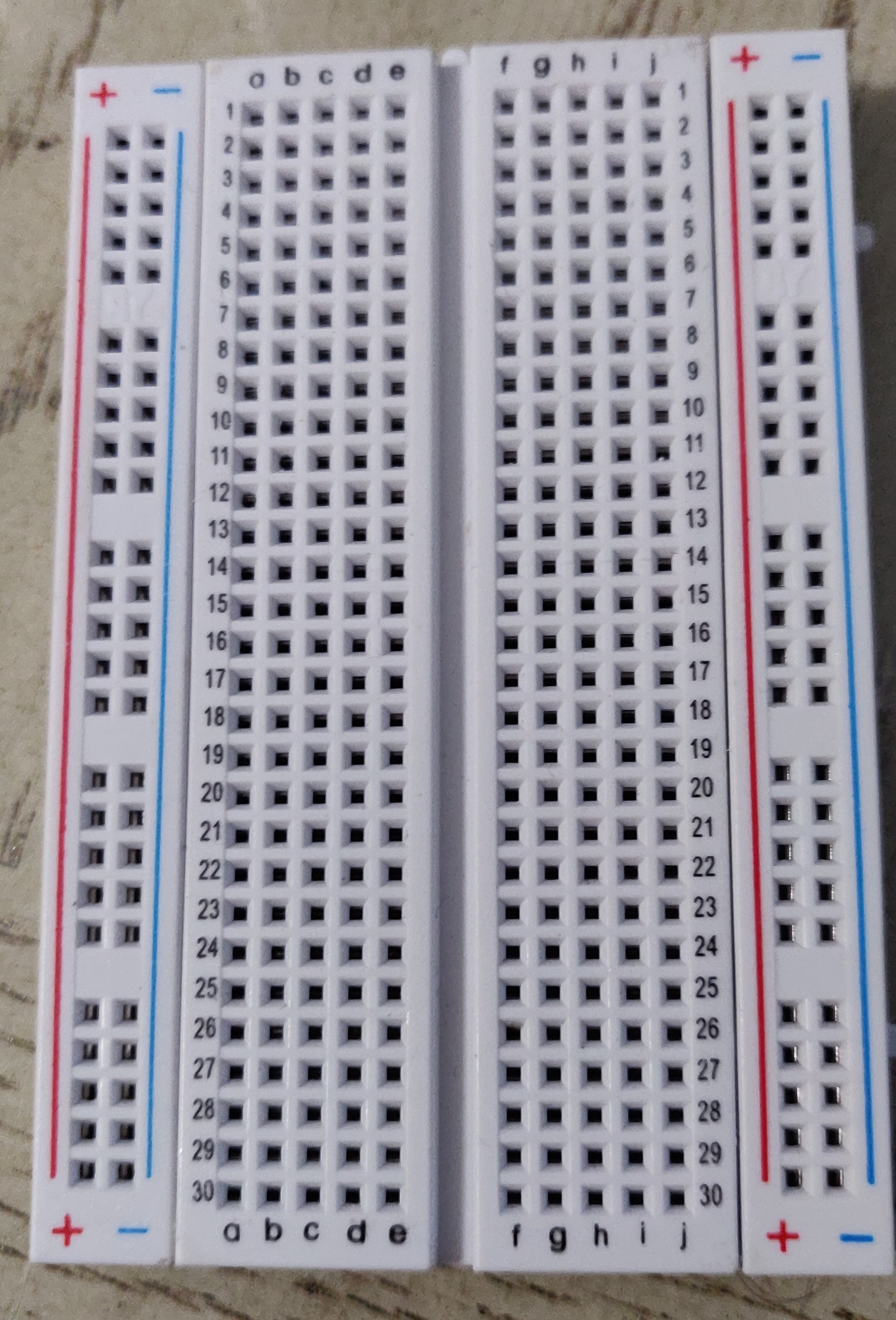
The breadboard is a way to build electronic prototype circuits without soldering. You connect components by pressing the components leads into the holes. Some holes are electrically connected and some are separated or electrically isolated. A great explanation of how a breadboard works can be found here.
We will be using the 4.8 volt power source pin on the Photon for our circuits. This pin can supply 1 Amp at 4.8 volts.

These are 6" long jumper wires with male connectors on both ends. These jumper wires can be used for pretty much everything! They work great with breadboards, Arduinos, and really any 0.1" pitch prototyping board. Each group of jumpers are connected to each other and can either be pulled apart in any quantity (from 1-20, of course) or kept whole based on you needs.

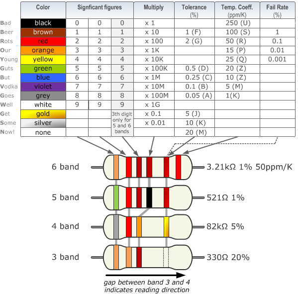
Your Resistor Kit contains all the resistors you will need to complete the labs experiments. Open your kit and lay the label printed side up on to the lid. The label now coincide with the resistors starting with 10 Ohms in the upper left. The resistors are coded with color bands. You can identify the resistance value using these bands or use your multimeter. It is always a good idea to verify the resistance value by using your multimeter.

A light-emitting diode (LED) is a semiconductor device that emits light when an electric current is passed through it. Light is produced when the particles that carry the current (known as electrons and holes) combine together within the semiconductor material. An incandescent lamp is a source of electric light that works by incandescence, which is the emission of light caused by heating the filament.
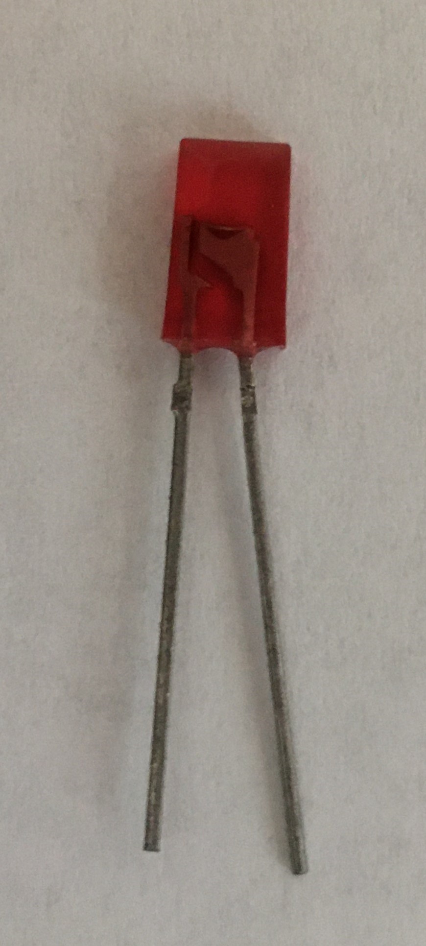
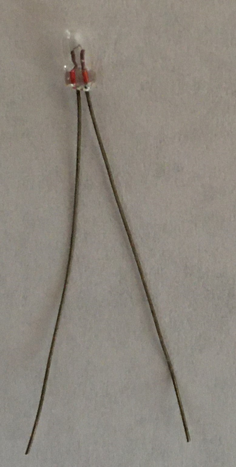
LED (Left Image) and Incandescent lamp (Right Image)
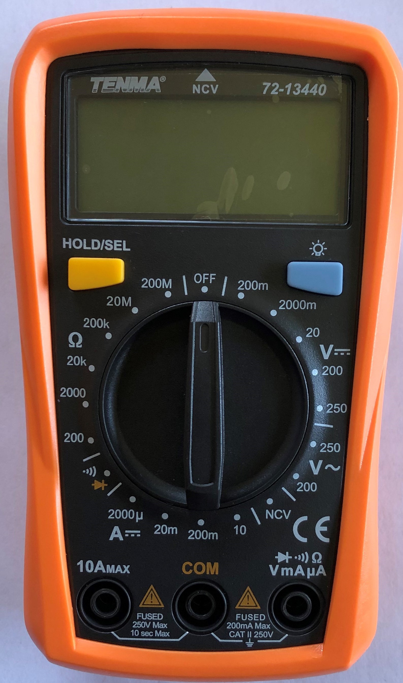
A Digital Multimeter is an instrument that can measure voltage, current, and resistance depending on the dial setting and how the leads are configured. Voltage is always measured in parallel and with respect to some other potential (in our case common). Current and resistance is measured in series. We will get into this in detail as we go through the experiments.
We will now review some of the basic electronic circuits that most of you have had in Physics. We'll then use the tools of this chapter to supply voltages and currents to your circuits and measure the outputs.

Recall that resistances in series add directly:
Equation 1.1
In parallel resistances add inversely:

For parallel resistors, the following equation for resistance applies.
Equation 1.2
The purpose of this exercise is to familiarize you with the handling of electronic components and construction of circuits on the Bread Board. Connect the 4.8 volt pin from your Photon to the resistor. Use a red wire and red banana to clip to connect your multimeter. Use a black wire and black banana to clip to connect to the ground pin of your Photon. Rotate the dial on your Multimeter to DC 200mA. Finaly, plug your Photon into the USB socket in your computer.

The sketch on this page shows connections literally, which we hope is helpful in learning to use the equipment. However, this is not an efficient means of communication. Whenever possible, we will instead use schematic diagrams, such as the equivalent shown below.

Figure 1 - Schematic Diagram of a Basic Resistive Circuit
NOTE on color coding: The laboratory standard when using a unipolar power supply is Red = +, Black = - (Ground or Common). When using a bipolar power supply Red = +, Black = -, Green = Ground. We will be using a unipolar power supply. As your circuits get more complicated, try to be consistent when choosing colors for connecting different inputs and outputs. It will make debugging your circuits much easier.
Exercise 1 - See worksheet for details.
Resistors slow the flow of electrons, and as a result, they have three basic functions:
- Connecting a resistor to the positive and negative terminals of a power supply will result in a unique current flowing through the resistor, given by Ohm’s law, so resistors convert voltage into current.
- When current flows through a resistor, there is a measurable voltage drop between the positive and negative sides. This voltage drop can be used to determine the current as per the relationship between current and voltage determined by Ohm’s law. As we will see, this is the basis for an essential diagnostic tool in circuit analysis.
- Because resistors slow the flow of electrons, in more complicated circuits, resistors limit the current through a circuit. Because of this behavior, resistors are often used to protect other components in a circuit.
If a known voltage is applied across a given resistance, a unique current will be generated. This relationship is given by Ohm's Law:
Equation 2
where V is the voltage in Volts, I is the current in Amps and R is the resistance in Ohms.
Replace the 1k resistor of your circuit with two resistors (which add up to near 1000Ω), as shown in Figure 2.
Exercise 2 - Use the multimeter to measure the voltage across each resistor. The current through the entire circuit will remain at 5mA, but there are two distinct voltages across R1 and R2 and both of these voltages can be used as signals to other devices. Use the measured voltages and the values of the resistors to calculate the current flowing through each resistor and record these values on the worksheet.
Most data acquisition devices (oscilloscope, computer data acquisition cards, Photon/Argon) measure only voltage, not current. When using one of these devices, this is the only way that current can be measured.

Figure 2 - Voltage Measured Across Resistors
An important function of resistors is the protection of circuit elements that can be damaged by excess current. This is because resistors limit the current through a circuit for a given voltage, as imposed by Ohm's law. A classic use of this current-limiting effect is protecting an LED (light-emitting diode). Using the LED supplied in your kit, build the circuit in Figure 3.

Figure 3 - Protected LED Circuit
NOTE: An LED is a true diode. An aspect of all diodes is they conduct in only one direction. Current flows from long lead to short, but we all inevitably forget this, so if the LED does not work, just turn it around. The Diode will not conduct until the avalanche voltage is reached. For the LED it’s 1.7 volts. After 1.7 volts, the diode has virtually no resistance. It is essentially a wire. Without the series 470Ω resistor, the diode would quickly burn out. A typical LED needs about 20mA.
Measure the current through the circuit. You should see about 7mA. Measure the voltage drop across D1 and R1 the same way you measured the voltage drop across the resistors in the previous exercise. Refer to Figure 2.4. You should measure about 1.7 volts and 3.3 volts respectively, a total of 5 volts. The current through the entire circuit can be calculated by subtracting the D1 voltage drop from the supply voltage (voltage at the 470Ω resistor) and using Ohms law.
Series circuits have the same current through each component; parallel circuits have the same voltage drop across each parallel component. We'll motivate the purpose of the parallel circuit by first building another series circuit.
Build the light bulb circuit in figure 4. Note the current and the bulb brightness and then, one at a time, wire in two more bulbs, as shown in figure 5. You should have noticed that as each light bulb was added, the resistance of the circuit increases so the current must decrease, and therefore the bulbs become dimmer with each additional bulb. Also note that if one light bulb were to burn out, the circuit is broken and all of the bulbs will turn off.

Figure 4 - Basic Incandescent Light Circuit
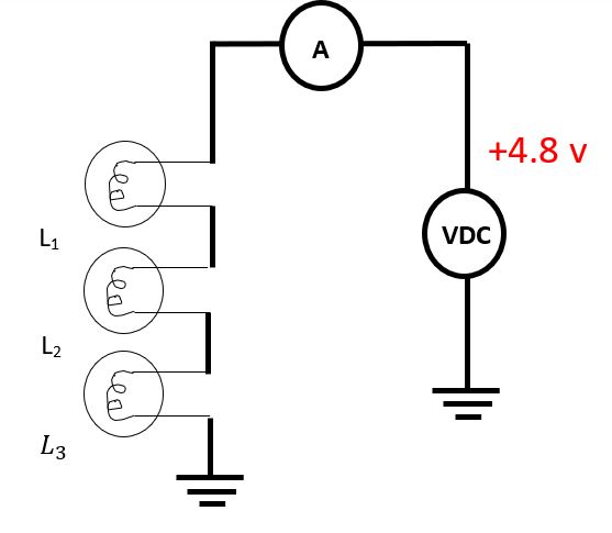
Figure 5 - Series Light Circuit
Now wire the bulbs in parallel, as shown in Figure 6, again installing each light bulb one at a time. Notice that the addition of each bulb has no effect on the brightness of the other bulbs. Also notice that as you add each bulb, you are effectively decreasing the resistance in the circuit, and therefore increasing the sum of the currents through all of the branches. Historically, the first city electrical systems were simply lights wired in series. Thomas Edison quickly recognized this problem with series circuits and designed the parallel circuit - an ingenious innovation for the time.
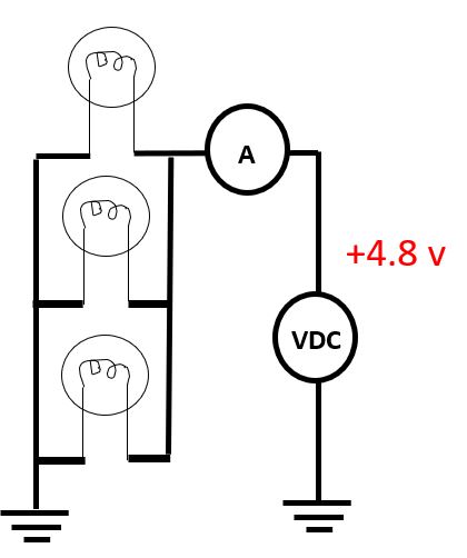
Figure 6 -Parallel Light Circuit
Replace the light bulbs with three resistors of your choice (greater than 500Ω), as shown in Figure 7q, and then using Equation 3, determine the equivalent resistance Req, and predict the current measured by the ammeter A in Figure 7b. Verify the theory, practice, and record your results in your notebook.
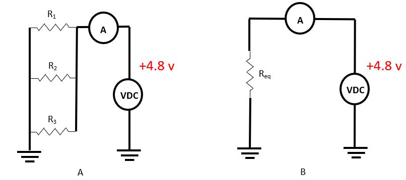
Figure 7 - Parallel Resistive Circuit and Resistive Equivalent (Req)
Exercise 3 - Complete questions from this section in the worksheet.
Figure 8 contains a voltage divider circuit. The transfer function for this circuit is
Equation 3
An essential assumption in the derivation of this equation (which you can, and should, easily derive) is that the output (Vout) draws no current. In reality, all loads draw some current. When designing circuits you must be aware of this current loading effect.
A typical voltage divider is shown in Figure 8. Construct this circuit and measure Vout⁄Vin. This should agree with Equation 3.
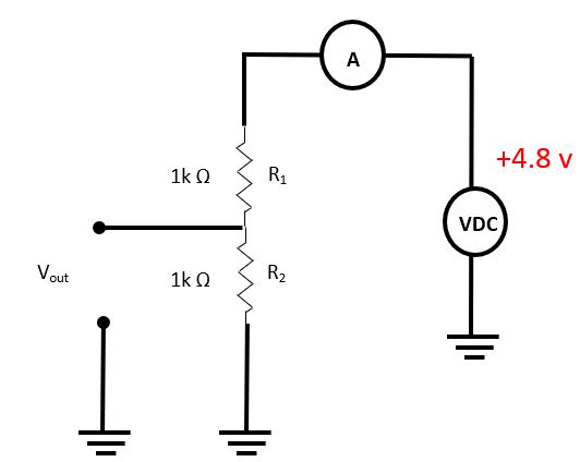
Figure 8 - Voltage Divider
Construct the circuit shown in Figure 9 only this time you will use your Photon as the Power Supply and multimeter. Connect the Photon Voltage Output Pin (use the DAC pin and label it 'A6' in matlab) to the long leg of the diode. Connect the Photon ground pin to the end of the resistor. Connect the Photon AI-0 pin to the junction of the diode and resistor. Refer to Figure 9. Run the program called Voltage_vs_Current_Curve.m". The Program steps the voltage out of the output pin .2 volts per second. AI-0 reads the voltage drop across the resistor and divides that voltage by the resistors value (in this case 470 Ω) to calculate the current in the circuit. In a series circuit, the current is the same throughout regardless of the number of components (conservation of charge). The program will plot current on the Y axis and voltage on the X axis. Now in the program change the 470 Ω resistor to a 1k resistor. Replace the 470 with a 1k in your circuit.
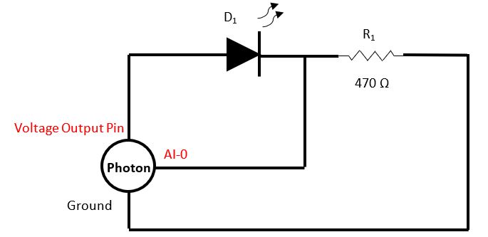
Figure 9 - LED Circuit
Exercise 4 - Copy graphs produced by the code above into the worksheet and explain why the current/voltage out slope changes with resistor value.