Spread Spectrum - LogeshVel/802.11 GitHub Wiki
modulation
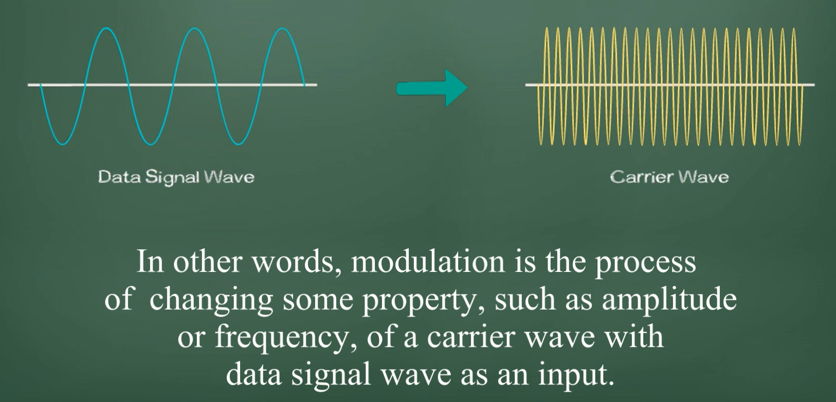
Consider a data signal (music, voice,...) we need a carrier wave to deliver our data signal.
In general, the frequency of carrier wave is higher than that of data signal.
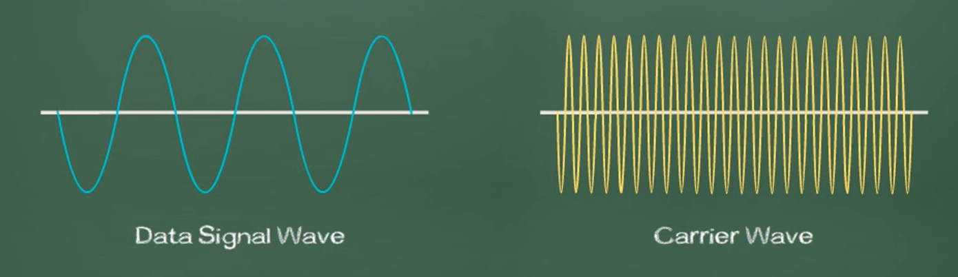
Modulation is the process of imposing a data signal wave onto a carrier wave.
why do we need modulation
Why don't we send data signal directly?
Lets take a example, if we throw a paper it can be throews to a shorter distance, if throw the paper by wrapping it with a stone it can move little far.
so here paper is the data signal and the stone is the carrier signal.
The same way, the need to modulation can be many reasons here are some
- Data signal wave is a low frequency signal wave (so it can't travel long distance)
Lower the frequency is more suspectible to interference than higher-frequency wave. Modulation makes the data signal wave a higher frequency wave.
-
Higher frequency wave would have more bandwidth and thus carrying more data.
-
lower frequency signals would require a much larger-size antenna at the receiving end.
Modulation reduce the antenna size with the increase of the wave frequency.
Why we need to use spread spectrum.
We could send the data(signals) in the single frequency, why do we need to use the spread spectrum instead of narrow band?

Types of spread spectrum
Frequency hopping (FH or FHSS)
Frequency-hopping systems jump from one frequency to another in a random pattern, transmitting a short burst at each subchannel. The 2-Mbps FH PHY is specified in clause 14.
Frequency-Hopping Transmission
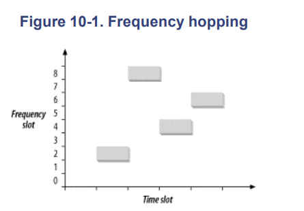
Frequency hopping depends on rapidly changing the transmission frequency in a predetermined, pseudorandom pattern. The vertical axis of the graph divides the available frequency into a number of slots. Likewise, time is divided into a series of slots. A hopping pattern controls how the slots are used.
In the figure, the hopping pattern is {2,8,4,7}. Timing the hops accurately is the key to success; both the transmitter and receiver must be synchronized so the receiver is always listening on the transmitter's frequency.
Frequency hopping is similar to frequency division multiple access (FDMA) but with an important twist. In FDMA systems, each device is allocated a fixed frequency. Multiple devices share the available radio spectrum by using different frequencies. In frequencyhopping systems, the frequency is time-dependent rather than fixed. Each frequency is used for a small amount of time, called the dwell time.
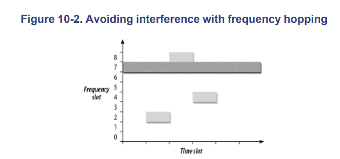
Among other things, frequency hopping allows devices to avoid interfering with primary users assigned to the same frequency band. It works because primary users are assigned narrow frequency bands and the right to transmit at a power high enough to override the wireless LAN. Any interference caused by the secondary user that affects the primary user is transient because the hopping sequence spreads the energy out over a wide band. Likewise, the primary user only knocks out one of the spread-spectrum device's slots and looks like transient noise.
Figure 10-2 shows the result when frequency slot 7 is given to a primary user. Although the transmission in the fourth time slot is corrupted, the first three transmissions succeed.
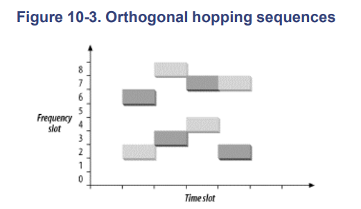
If two frequency-hopping systems need to share the same band, they can be configured with different hopping sequences so they do not interfere with each other. During each time slot, the two hopping sequences must be on different frequency slots. As long as the systems stay on different frequency slots, they do not interfere with each other.
The gray rectangles have a hopping sequence of {2,8,4,7}, as in the previous figures. A second system with a hopping sequence of {6,3,7,2} is added. Hopping sequences that do not overlap are called orthogonal. When multiple 802.11 networks are configured in a single area, orthogonal hopping sequences maximizes throughput.
Gaussian Frequency Shift Keying (GFSK)
The FH PHY uses Gaussian frequency shift keying (GFSK). Frequency shift keying encodes data as a series of frequency changes in a carrier. One advantage of using frequency to encode data is that noise usually changes the amplitude of a signal; modulation systems that ignore amplitude (broadcast FM radio, for example) tend to be relatively immune to noise. The Gaussian in GFSK refers to the shape of radio pulses; GFSK confines emissions to a relatively narrow spectral band and is thus appropriate for secondary uses. Signal processing techniques that prevent widespread leakage of RF energy are a good thing, particularly for secondary users of a frequency band. By reducing the potential for interference, GFSK makes it more likely that 802.11 wireless LANs can be built in an area where another user has priority.
Direct sequence (DS or DSSS)
Direct-sequence systems spread the power out over a wider frequency band using mathematical coding functions. Two direct-sequence layers were specified. The initial specification in clause 15 standardized a 2-Mbps PHY, and 802.11b added clause 18 for the HR/DSSS PHY.
Direct-sequence equipment requires more power to achieve the same throughput as a frequency-hopping system.
2 Mbps direct-sequence interfaces will drain battery power more quickly than 2-Mbps frequency-hopping interfaces.
The real advantage to direct-sequence transmission is that the technique is readily adaptable to much higher data rates than frequency-hopping networks.
Direct-sequence transmission is an alternative spread-spectrum technique that can be used to transmit a signal over a much wider frequency band.
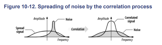
Changes in the radio carrier are present across a wide band, and receivers can perform correlation processes to look for changes.
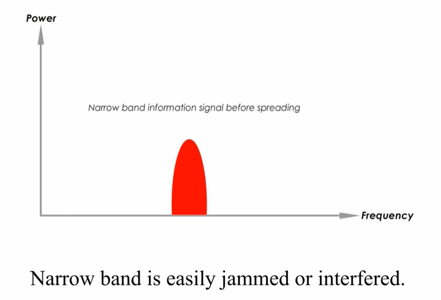
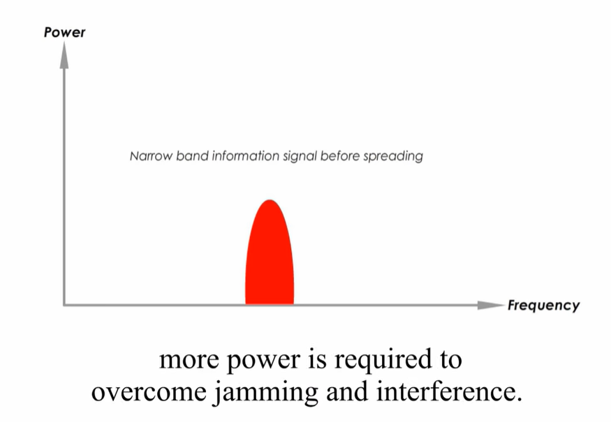
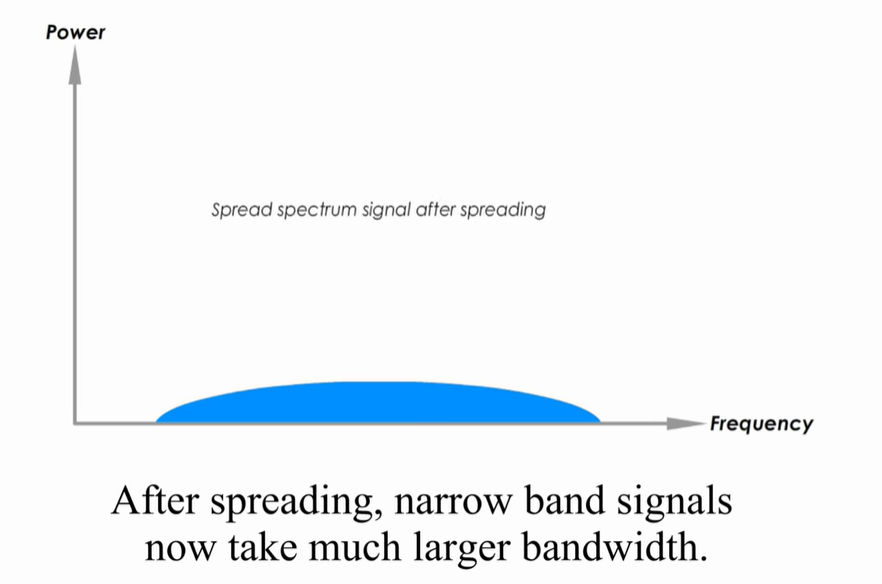
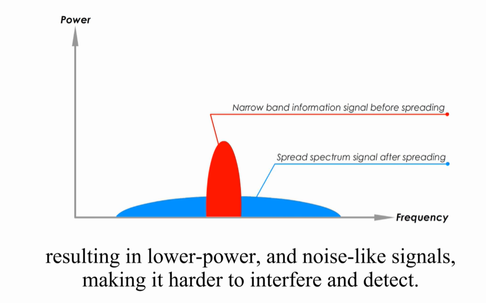
The Narrow band signal(all data in a single frequency) is spreaded across the wider band.
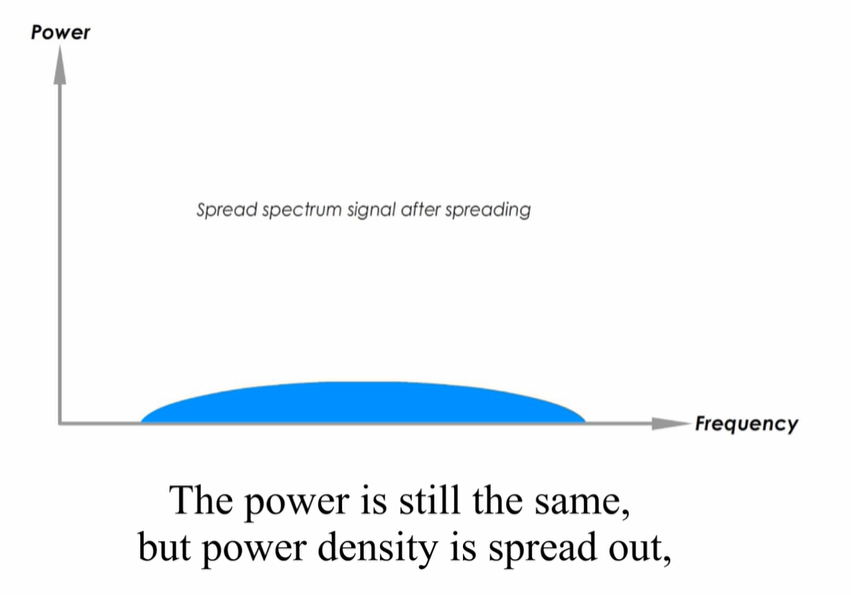
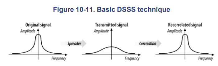
At the left is a traditional narrowband radio signal. It is processed by a spreader, which applies a mathematical transform to take a narrowband input and flatten the amplitude across a relatively wide frequency band. To a narrowband receiver, the transmitted signal looks like low-level noise because its RF energy is spread across a very wide band. The key to direct-sequence transmission is that any modulation of the RF carrier is also spread across the frequency band. Receivers can monitor a wide frequency band and look for changes that occur across the entire band. The original signal can be recovered with a correlator, which inverts the spreading process.
At a high level, a correlator simply looks for changes to the RF signal that occur across the entire frequency band. Correlation gives direct-sequence transmissions a great deal of protection against interference. Noise tends to take the form of relatively narrow pulses that, by definition, do not produce coherent effects across the entire frequency band. Therefore, the correlation function spreads out noise across the band, and the correlated signal shines through.
working
Direct-sequence modulation works by applying a chipping sequence to the data stream. A chip is a binary digit used by the spreading process. Bits are higher-level data, while chips are binary numbers used in the encoding process. There's no mathematical difference between a bit and a chip, but spread-spectrum developers have adopted this terminology to indicate that chips are only a part of the encoding and transmission process and do not carry any data. Chipping streams, which are also called pseudorandom noise codes (PN codes), must run at a much higher rate than the underlying data.
Several chips are used to encode a single bit into a series of chips. The high-frequency chipped signal is transmitted on an RF carrier. At the other end, a correlator compares the received signal to the same PN sequence to determine if the encoded bit was a or a 1.
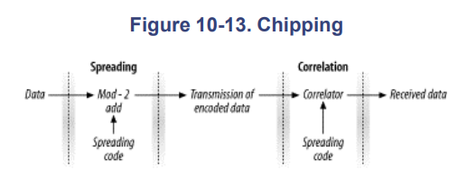
The process of encoding a low bit rate signal at a high chip rate has the side effect of spreading the signal's power over a much wider bandwidth. One of the most important quantities in a direct-sequence system is its spreading ratio, which is the number of chips used to transmit a single bit.
**Higher spreading ratios improve the ability to recover the transmitted signal but require a higher chipping rate and a larger frequency band. Doubling the spreading ratio requires doubling the chipping rate and doubles the required bandwidth as well. **
There are two costs to increased chipping ratios.
-
One is the direct cost of more expensive RF components operating at the higher frequency, and
-
the other is an indirect cost in the amount of bandwidth required.
Therefore, in designing directsequence systems for the real world, the spreading ratio should be as low as possible to meet design requirements and to avoid wasting bandwidth.
Direct-sequence modulation trades bandwidth for throughput. It is easier to achieve high throughput using direct-sequence techniques than with frequency hopping.
working example
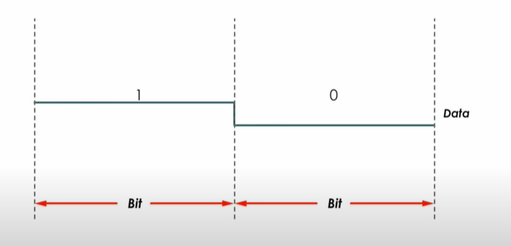
Suppose we send 2bit data 1 and 0.
In DSSS, we now encode this data with the PN sequence(Pseduonoise) or chips (Higher data/bit rate than the data)
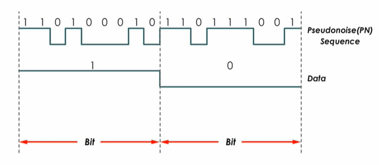
Now, we will use the XOR gate to encode and modulate the data.
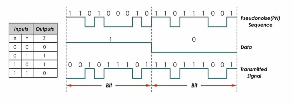
By doing so the 2 bit rate data is encoded and modulate to form higher data rate(narrow to spread).
This will be reversed by the correlator function at the receiver side.
High Rate DSSS - HR/DSSS
The initial version of the standard defined FH and DS PHYs, but they were only capable of data rates up to 2 Mbps.
802.11b adds another physical layer into the mix. It uses the same MAC as all the other physical layers and is based on direct-sequence modulation. However, it enables transmission at up to 11 Mbps, which is adequate for modern networks. Higher data rates led to a stunning commercial success. 802.11b has blazed new trails where other wireless technologies failed to make an impact. The 802.11b PHY is also known as the high-rate, direct-sequence PHY, abbreviated HR/DS or HR/DSSS. Even though the modulation is different, the operating channels are exactly the same as the channels used by the original low-rate direct sequence.
802.11 direct-sequence systems use a rate of 11 million chips per second. The original DS PHYs divided the chip stream up into a series of 11-bit Barker words and transmitted 1 million Barker words per second. Each word encoded either one bit or two bits for a corresponding data rate of 1.0 Mbps or 2.0 Mbps, respectively.
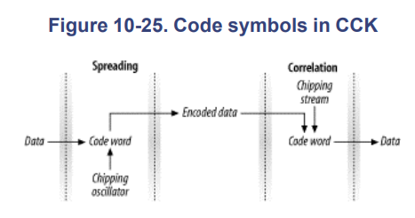
Complementary code keying
Instead of continuing with straight phase-shift keying, the IEEE 802.11 working group turned to an alternate encoding method. Complementary code keying (CCK) divides the chip stream into a series of 8-bit code symbols, so the underlying transmission is based on a series of 1.375 million code symbols per second. CCK is based on sophisticated mathematical transforms that allow the use of a few 8-bit sequences to encode 4 or even 8 bits per code word, for a data throughput of 5.5 Mbps or 11 Mbps. In addition, the mathematics underlying CCK transforms allow receivers to distinguish between different codes easily, even in the presence of interference and multipath fading.
It is quite similar to the chipping process used by the slower direct-sequence layers; the difference is that the code words are derived partially from the data.
CCK uses the code word to carry information, as well as simply to spread the signal. Several phase angles are used to prepare a complex code word of eight bits.
Orthogonal Frequency Division Multiplexing (OFDM)
OFDM is the variation of FDM(Frequency Division Multiplexing)
OFDM divides an available channel into several subchannels and encodes a portion of the signal across each subchannel in parallel. The technique is similar to the Discrete Multi-Tone (DMT) technique used by some DSL modems. Clause 17, added with 802.11a, specifies the OFDM PHY.
The 5-GHz bands that are reserved for unlicensed use are designated as the Unlicensed National Information Infrastructure (U-NII). The U-NII bands provide more spectrum space than the 2.4-GHz bands and are much less heavily used; there are very few devices on the market that operate in these bands. The 802.11a working group is responsible for developing physical layers for high-rate wireless service on the 5-GHz bands.
OFDM is closely related to plain old frequency division multiplexing (FDM). Both divide the available bandwidth into slices called carriers or subcarriers and make those carriers available as distinct channels for data transmission. OFDM boosts throughput by using several subcarriers in parallel and multiplexing data over the set of subcarriers.
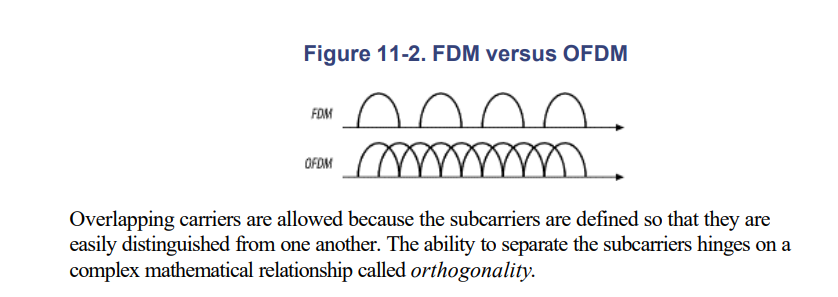
FDM
FDM allows multiple users to share one link by dividing available bandwidth into different non-overlapping sub channels. A Guard band, a narrow frequency range is inserted between adjacent sub channels so that different signals travel separately and simultaneously without interfering with each other.
In OFDM, those subchannels are place closely but actually they are overlapped. OFDM avoid interference by combining the user signal in a way they are orthognal to each other. Orthogonal means the 2 or more objects acts independently
Orthogonal Example:
Consider the 3 user signals which are placed orthogonal to each other.
- When one user signal is at its peak the reaming other signals are 0 or null.
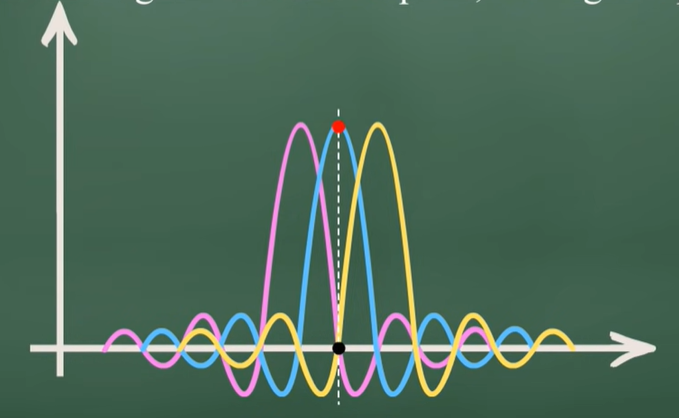
Orthogonal means signals are multiplexed in a way that the peak of one signal occurs at null of other neighbour signals.
At the receiver end the De-multiplexer separate them based on the orthogonal feature.
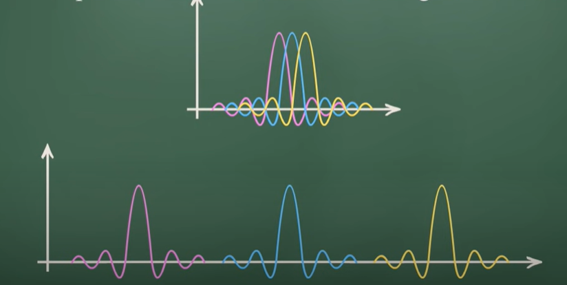
Each user was given an exclusive channel, and guard bands were used to ensure that spectral leakage from one user did not cause problems for users of adjacent channels.
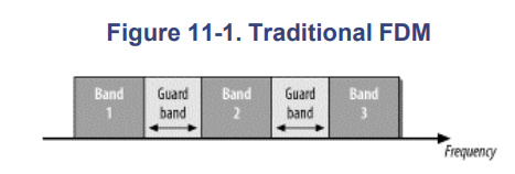
The trouble with traditional FDM is that the guard bands waste bandwidth and thus reduce capacity. To wasting transmission capacity with unused guard bands, OFDM selects channels that overlap but do not interfere with each other.