802.11 MAC - LogeshVel/802.11 GitHub Wiki
Collision avoidance built into the 802.11 MAC
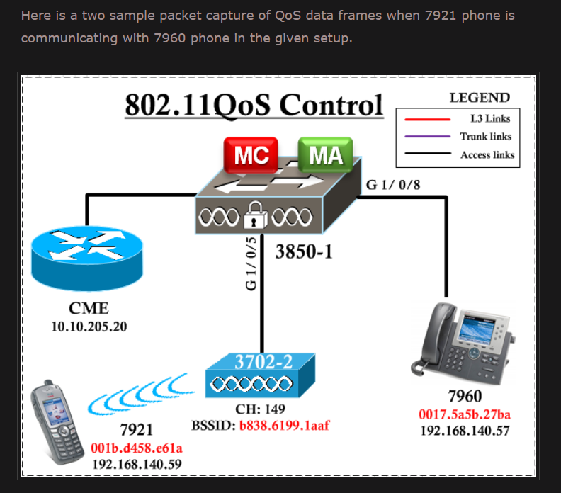
The split between source and transmitter is necessary because the 802.11 MAC sends acknowledgments to the frame's transmitter (the access point), but higher layers send replies to the frame's source.
Like Ethernet, 802.11 uses a carrier sense multiple access (CSMA) scheme to control access to the transmission medium. However, collisions waste valuable transmission capacity, so rather than the collision detection (CSMA/CD) employed by Ethernet, 802.11 uses collision avoidance (CSMA/CA). Also like Ethernet, 802.11 uses a distributed access scheme with no centralized controller. Each 802.11 station uses the same method to gain access to the medium. The major differences between 802.11 and Ethernet stem from the differences in the underlying medium.
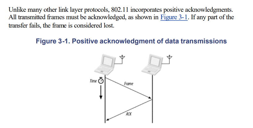
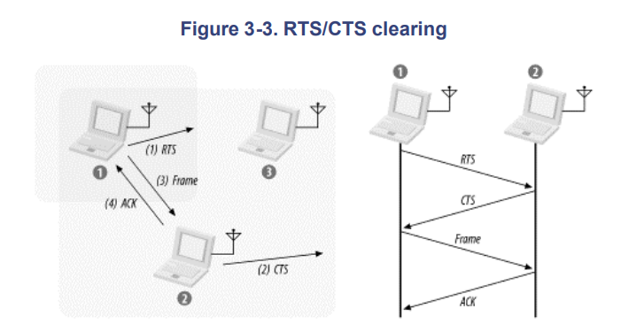
To prevent collisions, 802.11 allows stations to use Request to Send (RTS) and Clear to Send (CTS) signals to clear out an area.
MAC Access modes and Timing
-
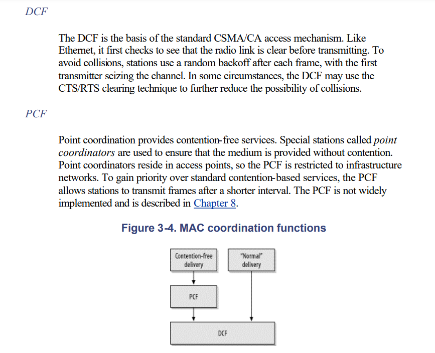
Distributed Coordination Function (DCF)
-
Point Coordination Function (PCF)
Carrier-Sensing Functions
Carrier sensing is used to determine if the medium is available. Two types of carriersensing functions in 802.11 manage this process:
-
the physical carrier-sensing and
-
virtual carrier-sensing functions.
If either carrier-sensing function indicates that the medium is busy, the MAC reports this to higher layers.
Physical carrier-sensing
Physical carrier-sensing functions are provided by the physical layer in question and depend on the medium and modulation used. It is difficult (or, more to the point, expensive) to build physical carrier-sensing hardware for RF-based media, because transceivers can transmit and receive simultaneously only if they incorporate expensive electronics. Furthermore, with hidden nodes potentially lurking everywhere, physical carrier-sensing cannot provide all the necessary information.
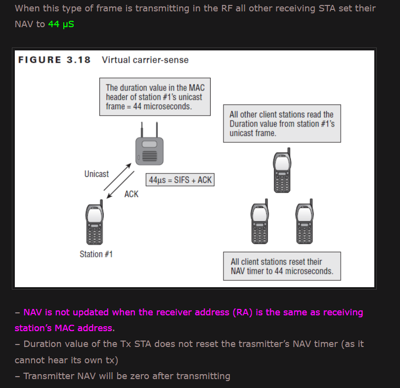
Virtual carrier-sensing
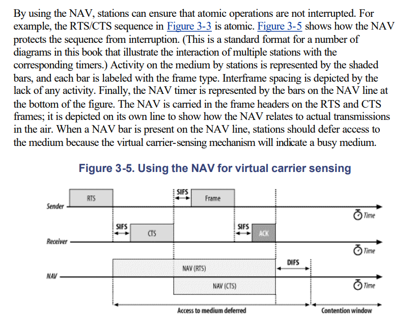
Virtual carrier-sensing is provided by the Network Allocation Vector (NAV). Most 802.11 frames carry a duration field, which can be used to reserve the medium for a fixed time period. The NAV is a timer that indicates the amount of time the medium will be reserved. Stations set the NAV to the time for which they expect to use the medium, including any frames necessary to complete the current operation. Other stations count down from the NAV to 0. When the NAV is nonzero, the virtual carrier-sensing function indicates that the medium is busy; when the NAV reaches 0, the virtual carrier-sensing function indicates that the medium is idle.
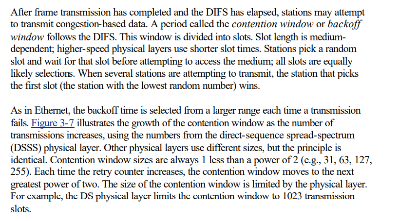
Contention window: If participants determine that the channel is free, they wait a random amount of time before they start sending. This duration corresponds to the contention window. This time window doubles with each collision and corresponds to the binary exponential backoff (BEB) that is familiar from CSMA/CD. Reference
Contention Window: It is the amount of time divided into slots. A station that is ready to send frames chooses a random number of slots as wait time.
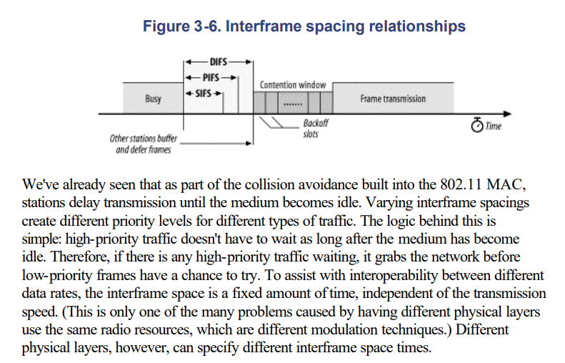
Interframe Spacing
When a station finds the channel busy it senses the channel again, when the station finds a channel to be idle it waits for a period of time called IFS time. IFS can also be used to define the priority of a station or a frame. Higher the IFS lower is the priority.
Contention-Based Access Using the DCF
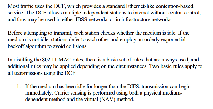
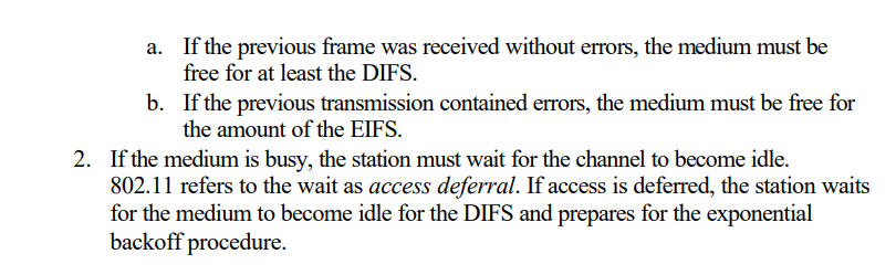
Additional rules may apply in certain situations. Many of these rules depend on the particular situation "on the wire" and are specific to the results of previous transmissions.
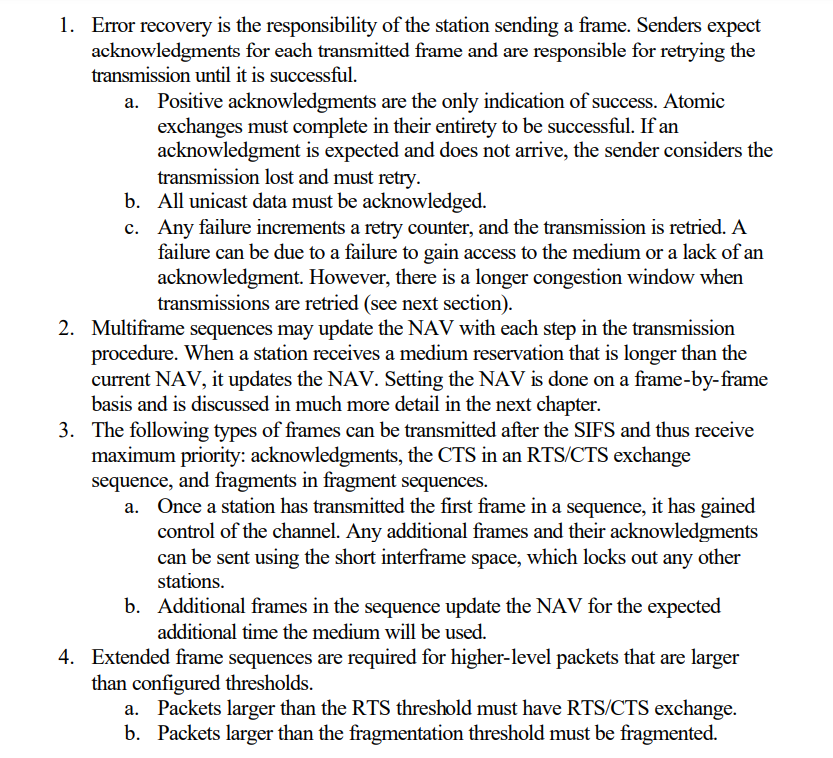
Error Recovery with the DCF
Error detection and correction is up to the station that begins an atomic frame exchange. When an error is detected, the station with data must resend the frame. Errors must be detected by the sending station. In some cases, the sender can infer frame loss by the lack of a positive acknowledgment from the receiver. Retry counters are incremented when frames are retransmitted.
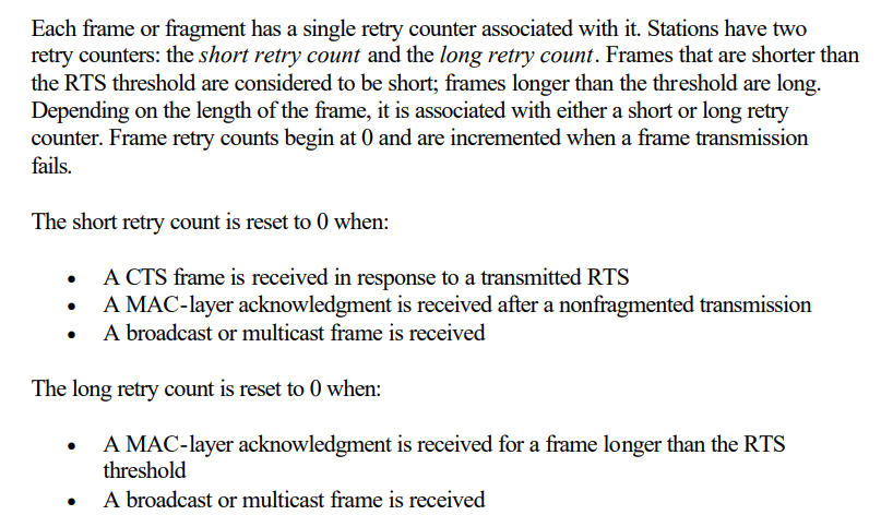
Backoff with the DCF
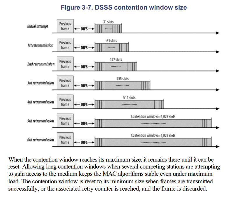
CSMA/CA
Good link to understand the csma/ca
CSMA/CA Flow
Fragmentation and Reassembly
Higher-level packets and some large management frames may need to be broken into smaller pieces to fit through the wireless channel. Fragmentation may also help improve reliability in the presence of interference. The primary sources of interference with 802.11 LANs are microwave ovens, with which they share the 2.4-GHz ISM band. Electromagnetic radiation is generated by the magnetron tube during its ramp-up and ramp-down, so microwaves emit interference half the time
Wireless LAN stations may attempt to fragment transmissions so that interference affects only small fragments, not large frames. By immediately reducing the amount of data that can be corrupted by interference, fragmentation may result in a higher effective throughput.
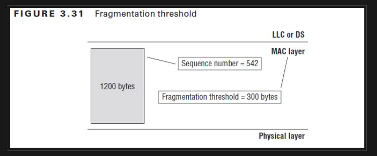
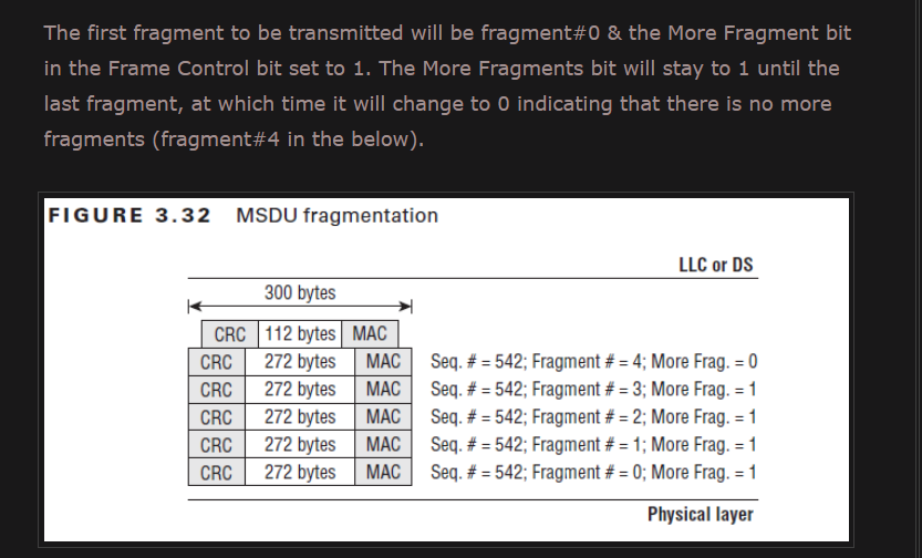
Fragmentation takes place when a higher-level packet's length exceeds the fragmentation threshold configured by the network administrator. Fragments all have the same frame sequence number but have ascending fragment numbers to aid in reassembly.
Frame control information also indicates whether more fragments are coming.
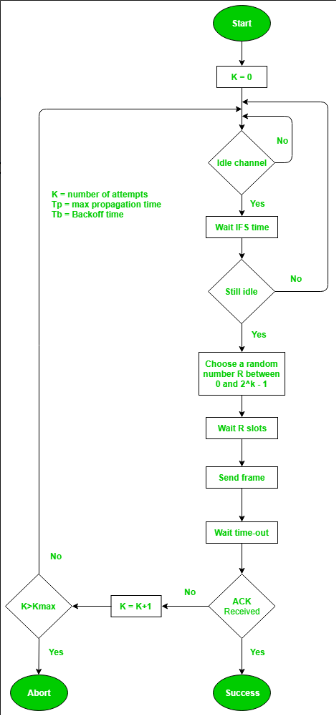
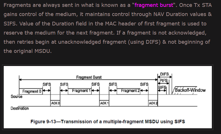
All of the fragments that comprise a frame are normally sent in a fragmentation burst.
Fragments and their acknowledgments are separated by the SIFS, so a station retains control of the channel during a fragmentation burst. The NAV is also used to ensure that other stations don't use the channel during the fragmentation burst.
As with any RTS/CTS exchange, the RTS and CTS both set the NAV from the expected time to the end of the first fragments in the air. Subsequent fragments then form a chain. Each fragment sets the NAV to hold the medium until the end of the acknowledgment for the next frame. Fragment 0 sets the NAV to hold the medium until ACK 1, fragment 1 sets the NAV to hold the medium until ACK 2, and so on. After the last fragment and its acknowledgment have been sent, the NAV is set to 0, indicating that the medium will be released after the fragmentation burst completes.
mrncciew - on 802.11 Fragmentation
Frame Format
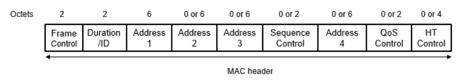
Not all frames use all the address fields, and the values assigned to the address fields may change depending on the type of MAC frame being transmitted.
802.11 MAC frames do not include some of the classic Ethernet frame features, most notably the type/length field and the preamble. The preamble is part of the physical layer, and encapsulation details such as type and length are present in the header on the data carried in the 802.11 frame.
Frame Control
Each frame starts with a two-byte Frame Control subfield
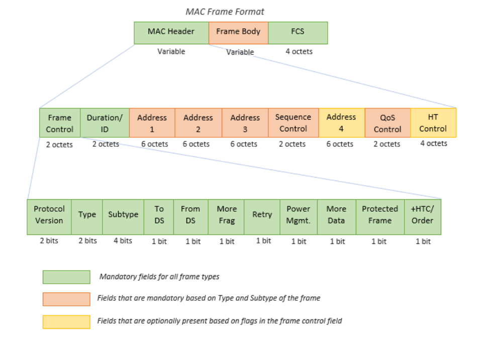
The components of the Frame Control subfield are:
Protocol version
Two bits indicate which version of the 802.11 MAC is contained in the rest of the frame. At present, only one version of the 802.11 MAC has been developed; it is assigned the protocol number 0.
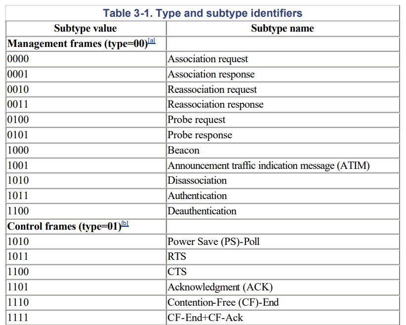
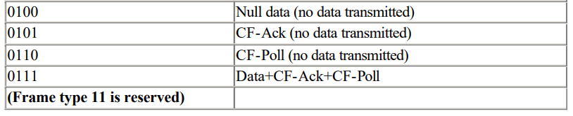
Type and subtype fields
Type and subtype fields identify the type of frame used. To cope with noise and unreliability, a number of management functions are incorporated into the 802.11 MAC. Some, such as the RTS/CTS operations and the acknowledgments.
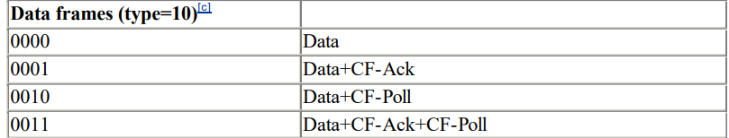
There are 3 types (Management, Control, Data) of wireless frames defined in the standard.
Type
00– Management Frame
01– Control Frame
10– Data Frame
11– Reserved
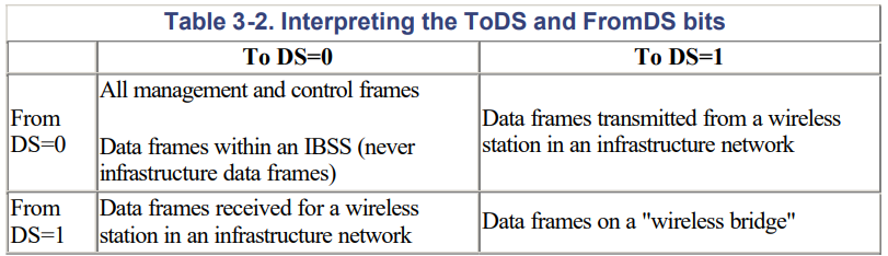
ToDS and FromDS bits
When ToDS set to “1” that indicate data frame is going from client station (STA) to Distribution System (DS)
When FromDS set to “1” that indicate data frame is going from Distribution System (DS) to client station (STA)
To DS=0, From DS=0
– It can be management or control frames where it does not go to DS
– Station to Station communication in IBSS (Independent Basic Service Set)
– STSL: Station to Station Link where data frame exchange direct client to client.
To DS=0, From DS=1
– Downstream traffic from AP to a client station.
To DS=1, From DS=0
– Upstream traffic from a client station to an AP.
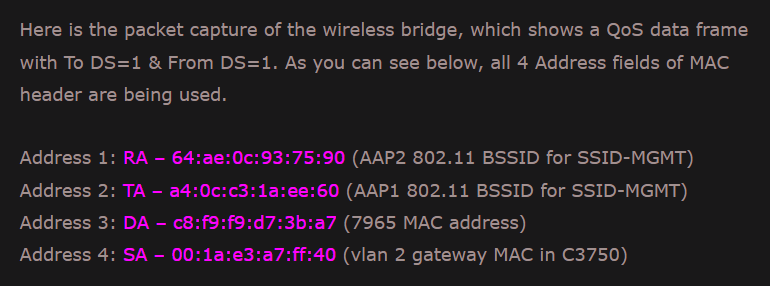
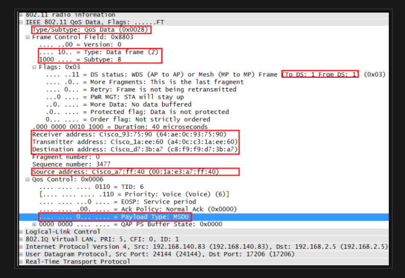
To DS=1, From DS=1
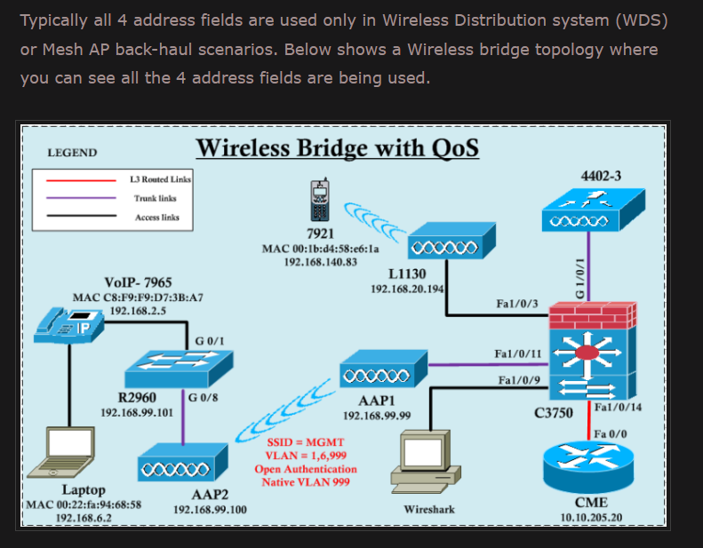
Data frames uses four address format.Usually occurs when Wireless Distribution System (WDS) in use, like Wireless Bridge or Mesh Network.
More fragments bit
This bit functions much like the "more fragments" bit in IP.
When a higher-level packet has been fragmented by the MAC, the initial fragment and any following nonfinal fragments set this bit to 1. Some management frames may be large enough to require fragmentation; all other frames set this bit to 0.
MAC layer fragments only those frame having unicast receiver address & never fragments broadcast or multicast frames (as those never get acknowledged)
Retry bit
From time to time, frames may be retransmitted. Any retransmitted frames set this bit to 1 to aid the receiving station in eliminating duplicate frames.
If Retry bit set to “1” in either a management frame or data frame, the Tx radio is indicating that the frame being sent is a “retransmission”. If a Tx station did not receive an ACK for a unicast frame, then frame will be retransmitted.
Excessive L2 retransmissions affect WLAN performance in two ways.
- Increases overhead resulting decreasing throughput
- impact timely delivery of application traffic (affect voice/video services)
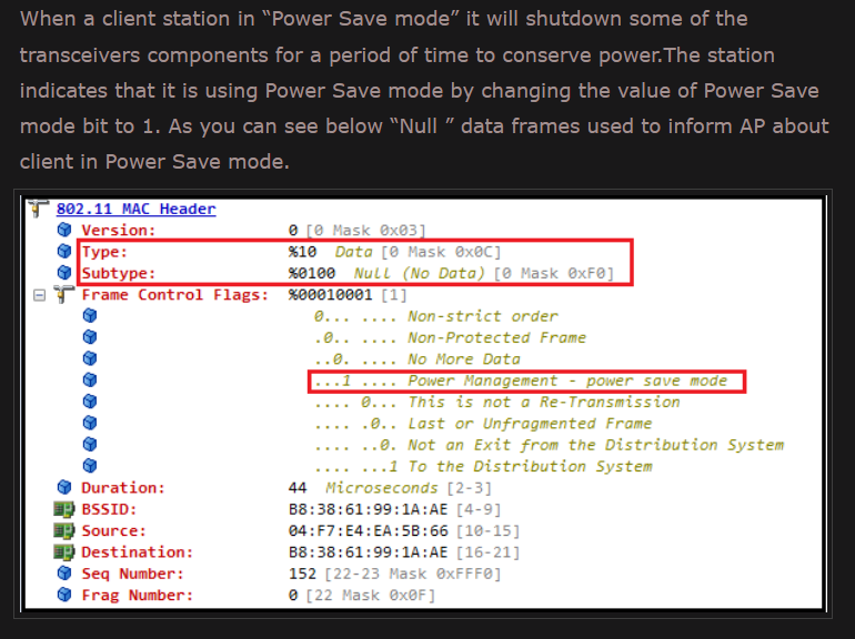
Power management bit
Network adapters built on 802.11 are often built to the PC Card form factor and used in battery-powered laptop or handheld computers.
To conserve battery life, many small devices have the ability to power down parts of the network interface.
This bit indicates whether the sender will be in a power-saving mode after the completion of the current atomic frame exchange.
1 indicates that the station will be in power-save mode, and 0 indicates that the station will be active.
Access points perform a number of important management functions and are not allowed to save power, so this bit is always 0 in frames transmitted by an access point.
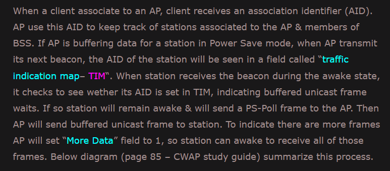
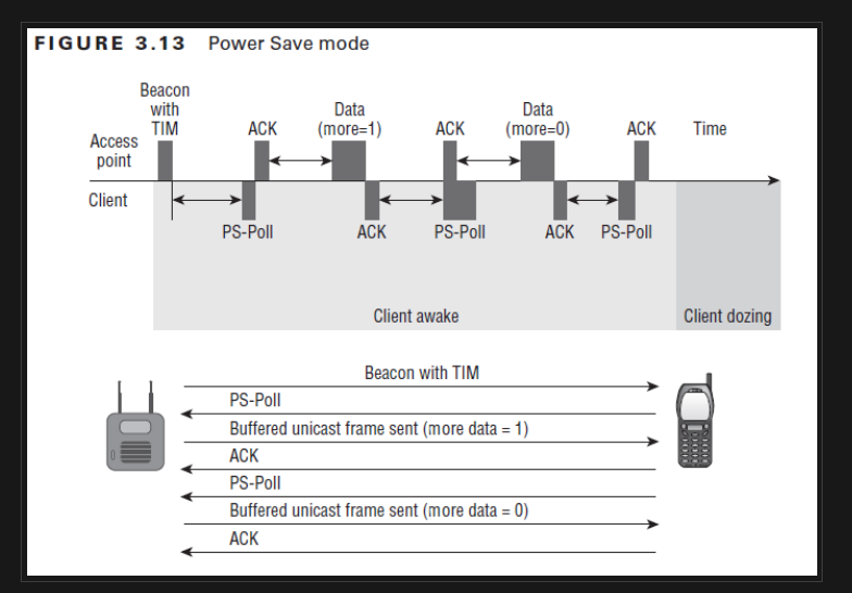
More data bit
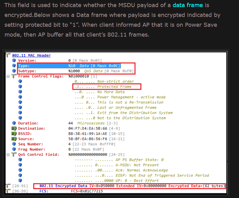
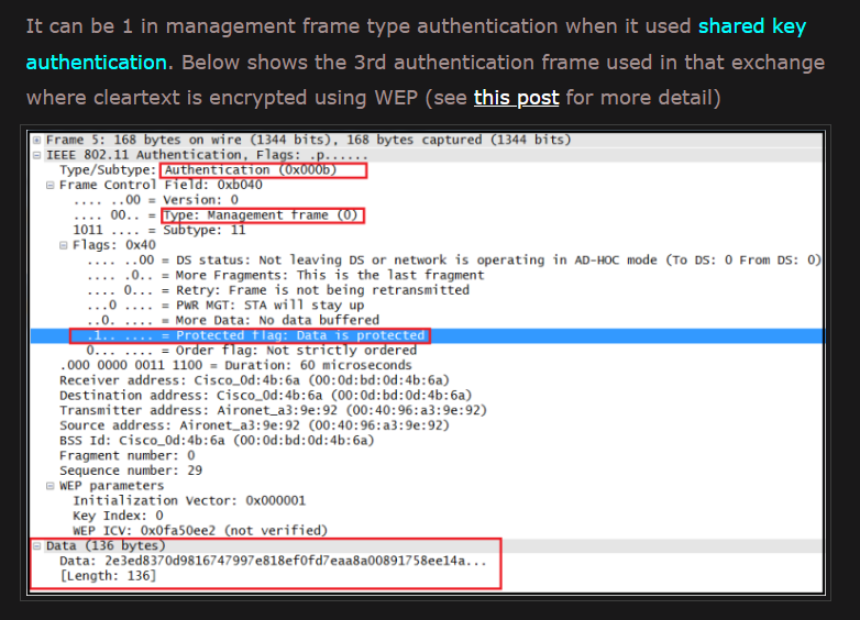
Protected Frame
Order
If it set to “1” in any non-QoS data frame when a higher layer has requested that the data be sent using a strictly ordered class of service, which tells the receiving station the frames must be processed in order. This field is set to “0” in all other frames.
Duration/ID
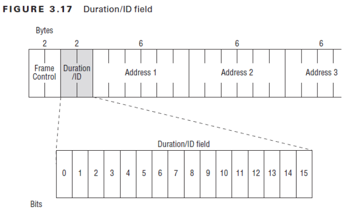
In 802.11, Duration/ID field can be used for 3 different reason
-
Virtual Carrier Sense (NAV) – This is the main purpose which used to reset the NAV timer of the other stations
-
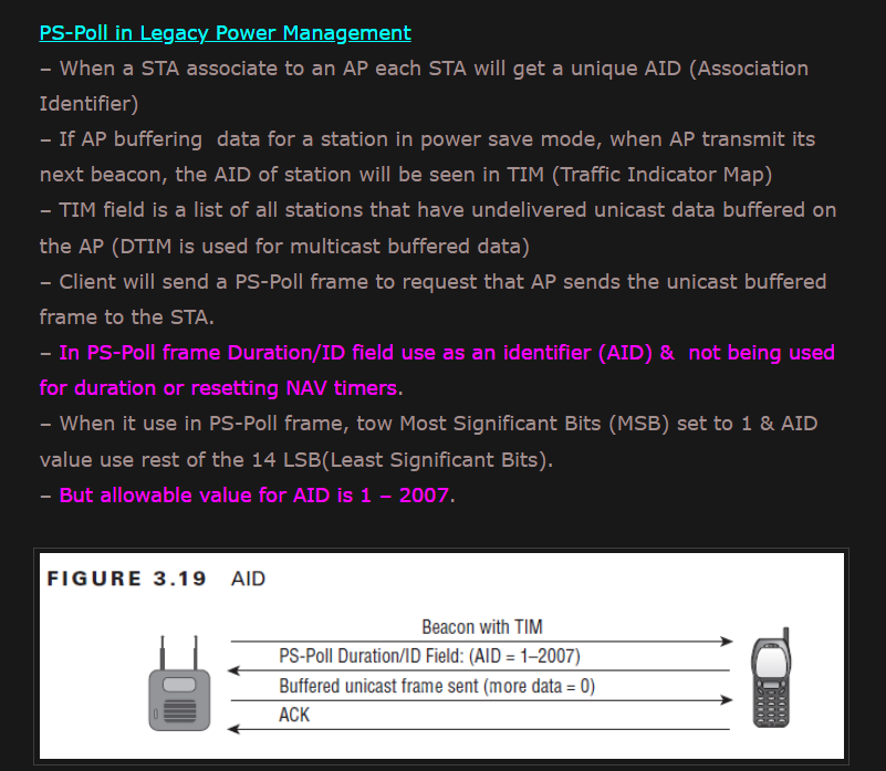
Legacy Power Management – PS Poll frames use this field as an association identifer (AID)
-
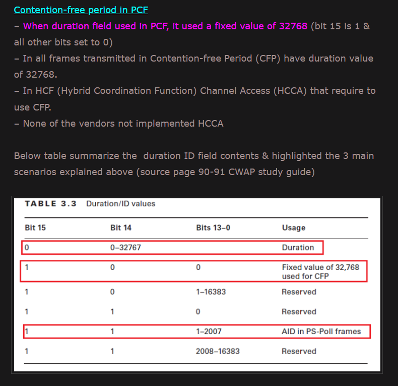
Contention-free Period – This field is used as an indicator that a point coordination function (PCF) process has begun.
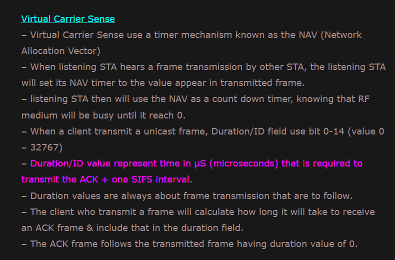
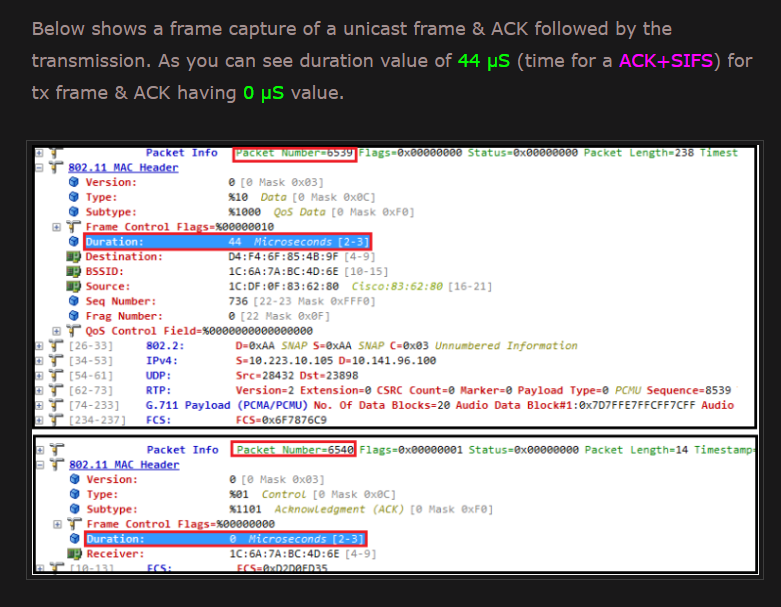
Virtual Carrier Sense
**When bit 15 is 0, the duration/ID field is used to set the NAV. **
The value represents the number of microseconds that the medium is expected to remain busy for the transmission currently in progress. All stations must monitor the headers of all frames they receive and update the NAV accordingly. Any value that extends the amount of time the medium is busy updates the NAV and blocks access to the medium for additional time.
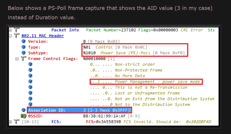
PS-Poll Frames
Bits 14 and 15 are both set to 1 in PS-Poll frames.
Mobile stations may elect to save battery power by turning off antennas. Dozing stations must wake up periodically. To ensure that no frames are lost, stations awaking from their slumber transmit a PS-Poll frame to retrieve any buffered frames from the access point. Along with this request, waking stations incorporate the association ID (AID) that indicates which BSS they belong to.
The AID is included in the PS-Poll frame and may range from 1-2,007. Values from 2,008-16,383 are reserved and not used.
Contention-free period in PCF
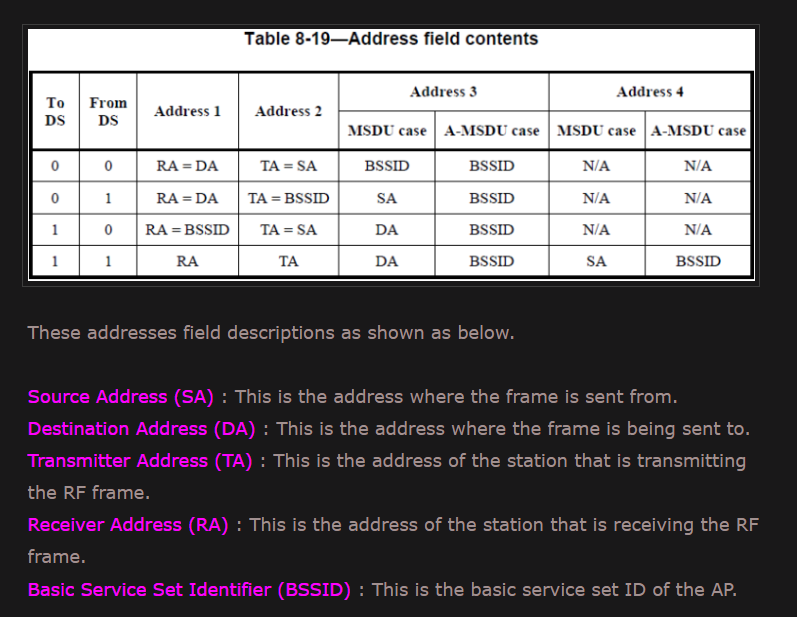
Address Fields
An 802.11 frame may contain up to four address fields. The address fields are numbered because different fields are used for different purposes depending on the frame type.
Note that Address 1 always holds the receiver address of the intended receiver, and that Address 2 always holds the address of the STA that is transmitting the frame.
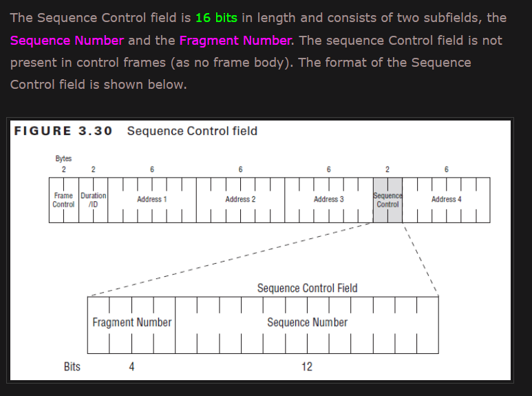
Sequence Control
This 16-bit field is used for both defragmentation and discarding duplicate frames.
It is composed of a 4-bit fragment number field and a 12-bit sequence number field.
Sequence Number
Sequence Number begins at 0 and increments by 1 for each higher-level packet handled by the MAC. If higher-level packets are fragmented, all fragments will have the same sequence number. When frames are retransmitted, the sequence number is not changed.
Fragment Number
The Fragment Number field is a 4-bit field indicating the number of each fragment of an MSDU or MMPDU. The fragment number is set to 0 in the first or only fragment of an MSDU or MMPDU and is incremented by one for each successive fragment of that MSDU or MMPDU. The fragment number remains constant in all retransmissions of the fragment.
Below shows an example for a STA configured with a fragmentation threshold (min 256 byte) of 300 bytes. So any MSDU larger than 300 bytes will be fragmented. Fragmentation does not take into account frame body expansion due to encryption, thus encrypted fragment may exceed the fragmentation threshold. Given example consider non-QoS data frame with MAC header size of 24 bytes (ie 32 -6 -2 bytes where 6 byte less for 4th address field & 2 bytes less for no QoS control field) and 4 byte CRC. So fragment size should be 272 bytes (300-28).
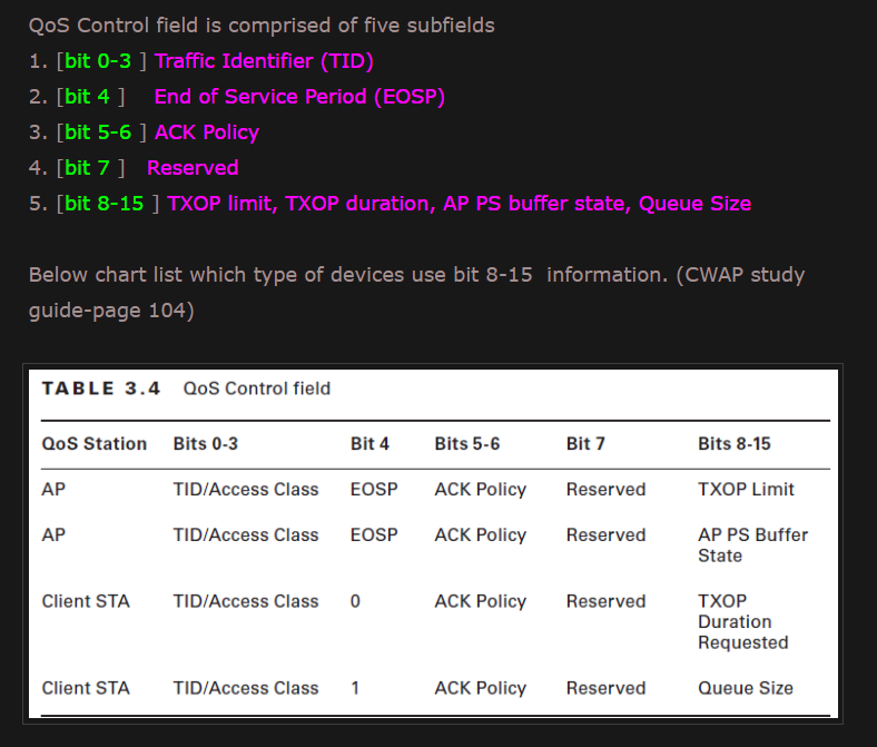
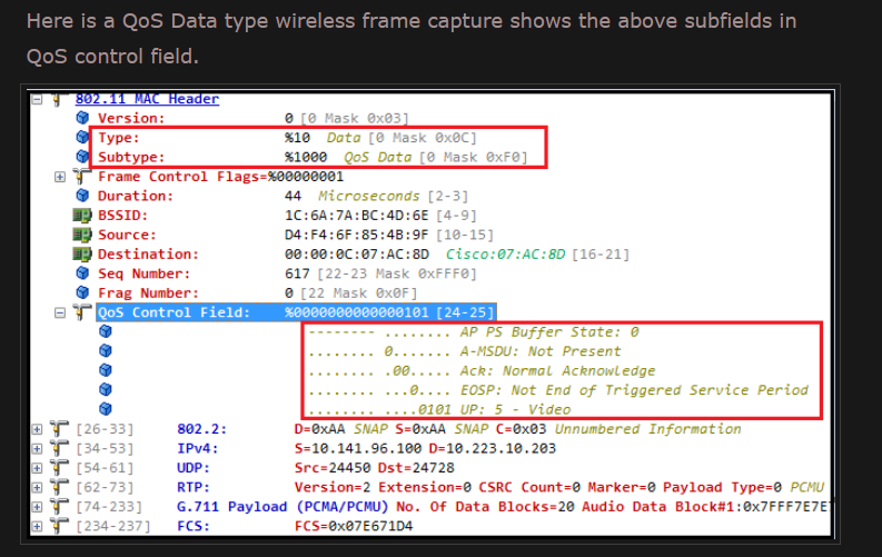
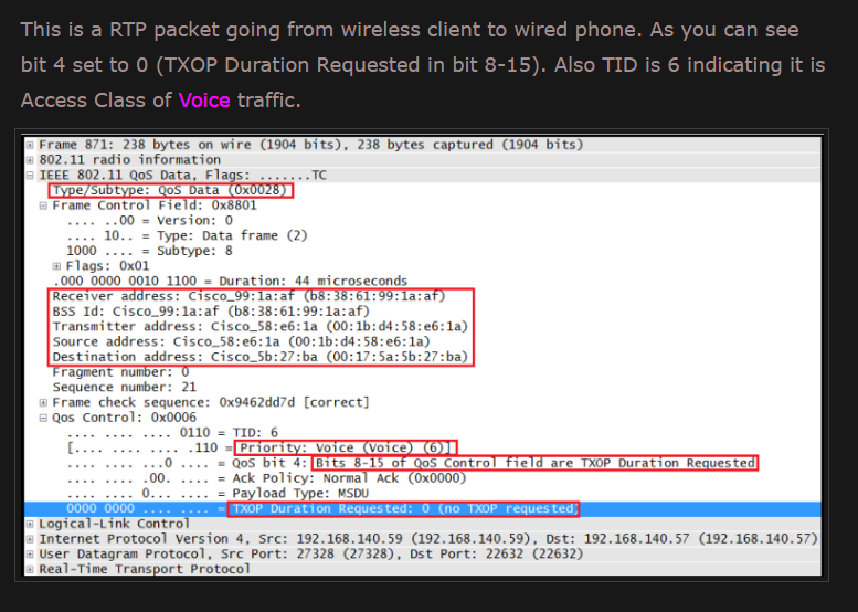
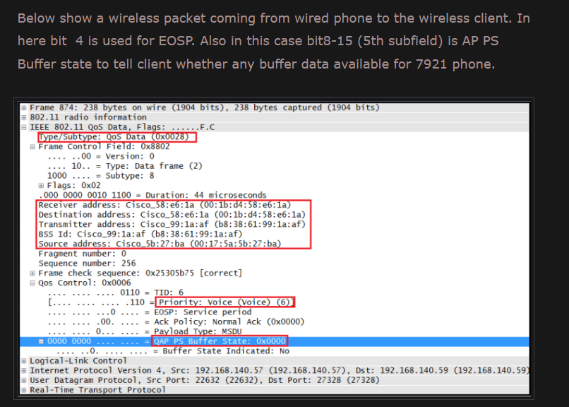
Qos Control
QoS Control is a 16-bit field that identifies the Quality of Service (QoS) parameter of a data frame (only in data frame type QoS-Data).
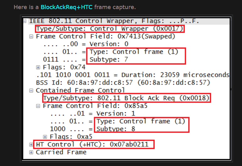
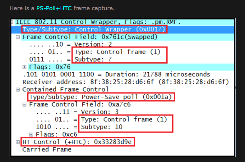
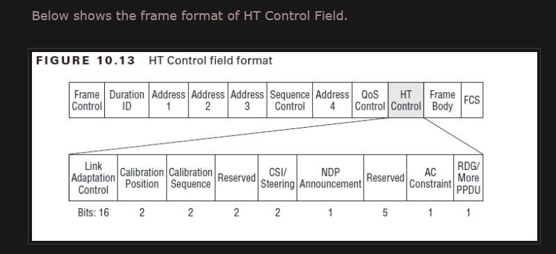
HT Control
4 Byte – HT Control (only for 802.11n frames)
The 802.11n amendment add a 4 byte HT control field to the 802.11 MAC header. With this HT Control field max MAC header length increased to 36 bytes.
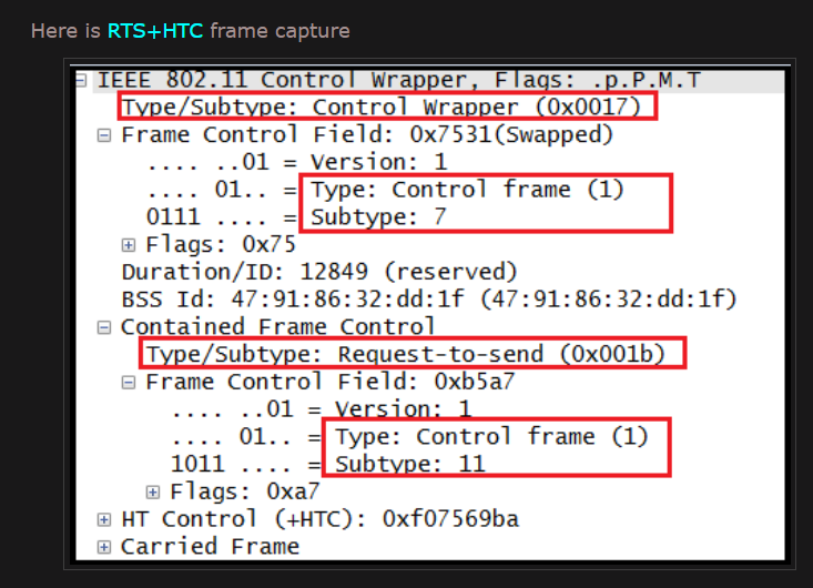
A control frame that is described as + HTC (eg RTS+HTC, BlockAckReq+HTC, PS-Poll+HTC) implies the use of Control Wrapper frame to carry the control frame.
Frame Body
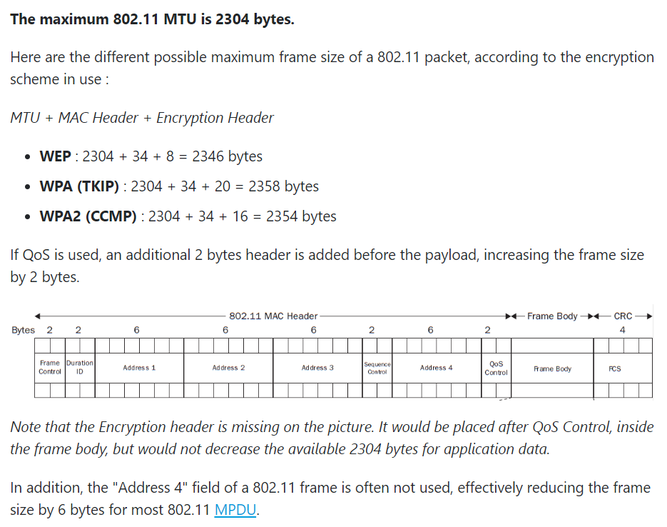
The frame body, also called the Data field, moves the higher-layer payload from station to station. 802.11 can transmit frames with a maximum payload of 2,304 bytes of higherlevel data. (Implementations must support frame bodies of 2,312 bytes to accommodate WEP overhead.)
802.11 MTU
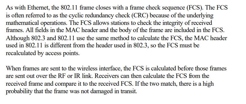
FCS