Home - LogeshVel/802.11 GitHub Wiki
802.11 Standard for Wireless Networks
802.11 Wireless Networks: The Definitive Guide
PHY Layer - Layer 1
The physical layer is responsible for various encoding and signaling functions that transform the data from bits that reside within a computer or other device into signals that can be sent over the network.
After encoding the data appropriately, the physical layer actually transmits the data, and of course, receives it. Note that this applies equally to wired and wireless networks, even if there is no tangible cable in a wireless network!
Ethernet, Wireless works in Layer 1 primarily. Also, the MAC sublayer of the Data Link layer
PHY layer of ethernet are Cables and for wireless it is radios
Data Link Layer - Layer 2
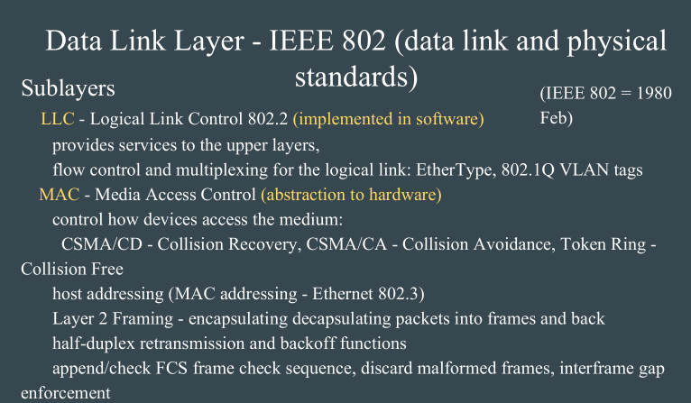
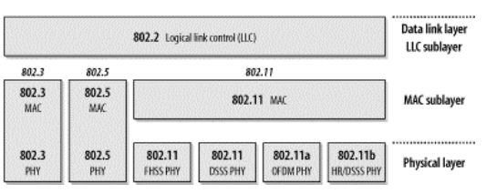
Has 2 sub layers
- Logical Link Control Sublayer (LLC - 802.2) , which is responsible for managing communications links and handling frame traffic. The general interface between the network layer (IP, IPX, etc) and the data link layer (Ethernet, Token Ring, Wireless etc). It is responsible for flow and error control. The LLC acts like a software bus allowing multiple higher layer protocols to access one or more lower layer networks. For example, if you have a server with multiple network interface cards, the LLC will forward packers from those upper layer protocols to the appropriate network interface. This allows the upper layer protocols to not need specific knowledge of the lower layer networks in use.
This upper sublayer defines the software processes that provide services to the network layer protocols. It places information in the frame that identifies which network layer protocol is being used for the frame. This information allows multiple Layer 3 protocols, such as IPv4 and IPv6, to utilize the same network interface and media.
- MAC Sublayer, which governs protocol access to the physical network medium. This lower sublayer defines the media access processes performed by the hardware. It provides data link layer addressing and delimiting of data according to the physical signaling requirements of the medium and the type of data link layer protocol in use.
Data Link Layer - TCP/IP guide
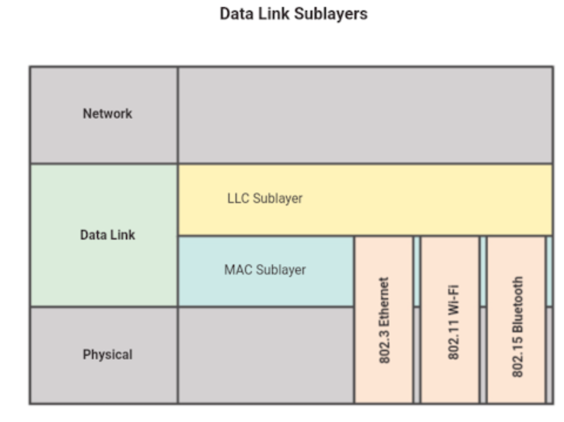
Radiotap Headers (PHY) of wireless
The 802.11 plus Radiotap header gives you Radiotap link-layer information followed by an 802.11 frame. Radiotap is a common mechanism for drivers to supply additional information about received frames to user space applications, or for user space applications to the driver for frames that will be transmitted. The Radiotap header format allows to include an arbitrary number of fields, which means that some fields might or might not be present depending on the driver’s implementation.
Frame Headers of wireless
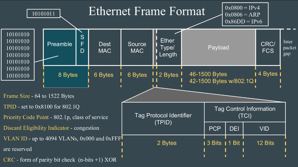
Frame Headers of ethernet
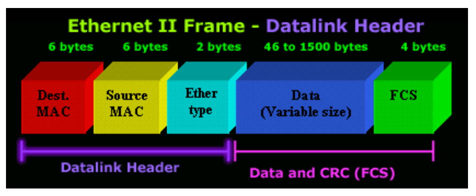
Frame formats of ethernet and wifi
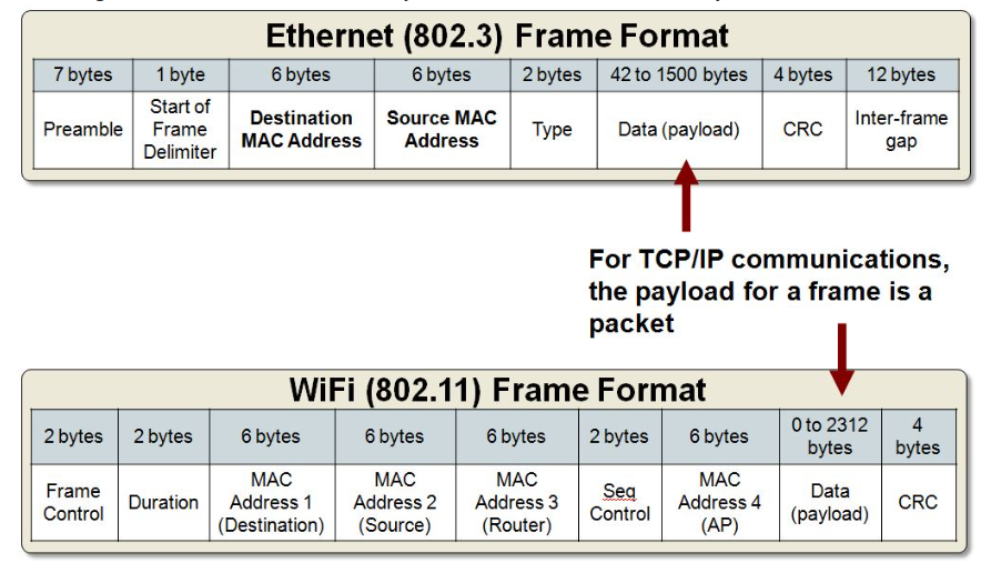
802.3 Ethernet
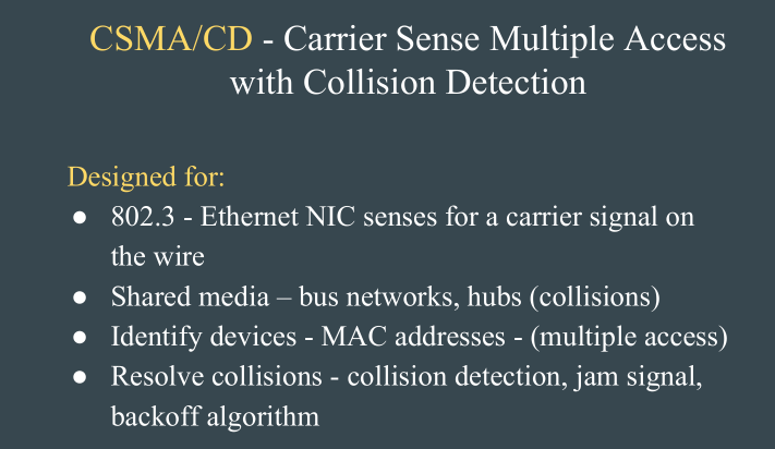
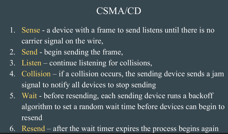
802.3 is the standard which Ethernet operates by. It is the standard for CSMA/CD (Carrier Sense Multiple Access with Collision Detection). This standard encompasses both the MAC and Physical Layer standards.
CSMA/CD is what Ethernet uses to control access to the network medium (network cable). If there is no data, any node may attempt to transmit, if the nodes detect a collision, both stop transmitting and wait a random amount of time before retransmitting the data.
The original 802.3 standard is 10 Mbps (Megabits per second). 802.3u defined the 100 Mbps (Fast Ethernet) standard, 802.3z/802.3ab defined 1000 Mbps Gigabit Ethernet, and 802.3ae define 10 Gigabit Ethernet.
Commonly, Ethernet networks transmit data in packets, or small bits of information. A packet can be a minimum size of 72 bytes or a maximum of 1518 bytes.
The most common topology for Ethernet is the star topology.
802.5 Token Ring
The token is a special frame which is designed to travel from node to node around the ring. When it does not have any data attached to it, a node on the network can modify the frame, attach its data and transmit. Each node on the network checks the token as it passes to see if the data is intended for that node, if it is; it accepts the data and transmits a new token. If it is not intended for that node, it retransmits the token on to the next node.
The token ring network is designed in such a way that each node on the network is guaranteed access to the token at some point. This equalizes the data transfer on the network. This is different from an Ethernet network where each workstation has equal access to grab the available bandwidth, with the possible of a node using more bandwidth than other nodes.
Originally, token ring operated at a speed of about 4 Mbps and 16 Mbps. 802.5t allows for 100 Mbps speeds and 802.5v provides for 1 Gbps over fibber.
Token ring can be run over a star topology as well as the ring topology.
There are three major cable types for token ring: Unshielded twisted pair (UTP), Shielded twisted pair (STP), and fibber.
Token ring utilizes a Multi-station Access Unit (MAU) as a central wiring hub. This is also sometimes called a MSAU when referring to token ring networks.
802.11 Wireless Network Standards
802.11 is the collection of standards setup for wireless networking.
Wireless LANs primarily use CSMA/CA - Carrier Sense Multiple Access/Collision Avoidance. It has a "listen before talk" method of minimizing collisions on the wireless network. This results in less need for retransmitting data.
Ethernet vs Wireless
802.3 is the specification for a Carrier Sense Multiple Access network with Collision Detection (CSMA/CD)
802.5 is the Token Ring specification
802.11 is just another link layer that can use the 802.2/LLC encapsulation
The PHY layer for the Ethernet and Token rings are same cables.
But for the Wireless the PHY layer is Radio waves.
The PHY Layers of 802.11
-
frequencyhopping spread-spectrum (FHSS)
-
direct-sequence spread-spectrum (DSSS)
-
High rate direct-sequence spread-spectrum (HR/DSSS)
-
orthogonal frequency division multiplexing (OFDM)
Spread Spectrum
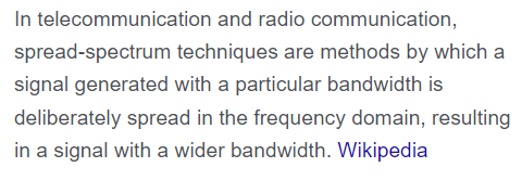
Telecommunications techniques in which a signal is transmitted in a bandwidth considerably greater than the frequency content of the original information.
Frequency hopping, direct sequence spreading, time scrambling, and combinations of these techniques are forms of spread spectrum.