0.Gathering pertinent information - L-division-2020-2021-odd/Repo-14 GitHub Wiki
Information gathered from various sources
| SI.NO | Components or Parts used (ELECTRONIC/MECHANICAL) | Mechanism/working principle identified | Links |
|---|---|---|---|
| 1 | Arduino (UNO,NANO R3), Arduino Uno | It is a microcontroller board based on ATmega328 which has 14 digital I/O and 6 analog pins. It has everything that is needed to support the microcontroller. Simply connect it to the computer with a USB cable to get started with the Arduino Uno board. It is flexible, easy to use hardware and software. Arduino Uno can sense the environment by receiving input from a variety of sensors and can affect its surroundings by controlling lights, motors, and other actuators. | https://youtu.be/_ItSHuIJAJ8 |
| 2 | Transmitter receiver, Encoder and decoder | The transmitter module is working on the frequency of 433MHz. In the circuit, Vcc pin is connected to the + terminal. The data pin is connected to the HT12E (Encoder) that is transmitted or we can say that encoded data. The next pin is GND that is connected to the ground terminal. Now the last pin ANT this is connected to a small wire as an antenna. The RF receiver module will receive the data which is transferred by the gesture device. It is also working as similar to the transmitter module- Connect the +Vcc pin to the 5volt terminal. Connect the ground pin to the ground terminal .The data pin is then connected to the HT12D | https://youtu.be/98tYLEnevfA |
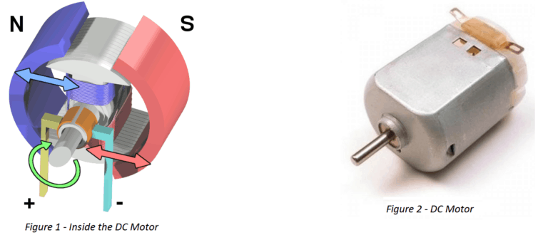
| 3 | DC motor, DC Gear motor | DC motor is used for the conversion of direct current into mechanical motion. The mechanical motion could be rotary or linear. The operation of DC motor is based on the principle that when a current carrying conductor is placed in a magnetic field, the conductor experiences a mechanical force. The speed of a DC motor can be controlled by changing the voltage applied to the armature or by changing the field current. DC motors can be used for the movement of the robotic car. | https://youtu.be/GPVC84D5ULw ,https://youtu.be/QMVYvtkFPEI |
| 4 | Motor driver IC | Motor Driver works on the concept of H-bridge. H-bridge is a circuit which allows the voltage to flow in either direction. As voltage need to change its direction for being able to rotate the motor in clockwise or anti-clockwise direction. Therefore H-bridge IC is ideal for driving a DC motor. In a single L293D chip there are two h-Bridge circuit inside the IC which can rotate two dc motor independently. Due to its size it is very much used in robotic application for controlling DC motors. | https://youtu.be/9ShJ6IH0ZLs |
| 5 | Accelerometer | The ADXL335 is a small, thin, low power, complete 3-axis accelerometer with signal conditioned voltage outputs. It has 6 pins. 3 pins is for X, Y, Z axis. First pin for power supply (VCC), second pin for ground (GND) and the last one for selftest (ST). It operates on 3.3V from the Arduino Uno board. X and Y axis pins are connected to A0 and A1 pin of Arduino Uno board respectively. It can measure the static acceleration of gravity from tilt sensing applications as well as dynamic acceleration resulting from motion, shock or vibration and gives corresponding analog values through X, Y, Z axis pins. The ADXL335 is available in a small, low profile, 4mm x 4mm x 1.45 mm, 16-lead, plastic lead frame chip scale package. | https://youtu.be/T_iXLNkkjFo |
Components
Accelerometer
The function of the accelerometer is simple: to sense the orientation of the wrist. The accelerometer measures acceleration including the acceleration due to gravity 'g' as well. Thus we can use the accelerometer to sense the orientation of the wrist by measuring the component of 'g' in any particular axis of ADXL335. Due to tilt of hand, the X and/or Y axis' angle with vertical changes and hence a component of 'g' acceleration acts upon them as well which can be measured and thus indicates the orientation of the hand.
The ADXL335 can measure up to 3g of acceleration and is interfaced with Arduino by connecting it's axis pins to Analog pins of Arduino. The accelerometer outputs voltage values proportional to acceleration.
In this project, Accelerometer is connected to Arduino Nano and is attached to the palm. The ADXL335 outputs voltage in range from 0 to Vcc (Applied voltage usually 3.3V) and is read by Arduino's Analog pins. Thus for the user, we get a value in range from 0 to 1024 (10-bit ADC). The different orientation yields a different analog value for each axis which is then mapped to different robot movements.

Transmitter and receiver
The function of RF module is simple: to transmit command data from wrist Arduino Nano to the motor controlling Arduino Uno. The RF module uses Radio waves at 433hz frequency and thus the name RF-433. They use Amplitude Modulation to send data, but not getting into much technicalities and keeping things simple, they will be used to transmit command to the robot, that is: move forward, backward, right or left. And in case of no data, stand still. They work well up to 10 meter range.
Transmitter Circuit: The transmitter circuit consist of two parts: the Transmitter RF and the Encoder HT12E. The Transmitter consist of one data pin, one antenna, one ground and power. It is the work of HT12E encoder to provide data to the transmitter. The encoder consists of 4 data pins whose data can be sent. We will use these 4 data pins to represent the four motions, a HIGH on these pins individually will represent one of the four motions and a LOW on all represents stand still. The left hand pins (A0-A7) are the address pins and define the pair which will exchange data (Transmitter and Receiver having same addresses will only share data). We will set A0-A7 as LOW (Grounded). The Data In pins are connected to Arduino digital pins (in this project 6 to 9) and they will output the command data as: Digital Pin Command (When HIGH) 9 Forward 10 Reverse 11 Left 12 Right We will digital Write the digital pins as HIGH based upon the input from ADXL335 to perform the required motion.

Receiver circuit: The receiver circuit is completely similar to the transmitter circuit as shown, but instead of data pins going as output from Arduino, in this case they will be read as inputs to take in the command for Arduino Uno and run the motors as required: To simplify, you can connect the LED in series at pin 17 with a 1K resistor instead of the complex circuit as shown to indicate proper connection with transmitter.

Arduino UNO
The ATmega328 is one kind of single-chip microcontroller formed with Atmel within the megaAVR family. The architecture of this Arduino Uno is a customized Harvard architecture with 8 bit RISC processor core. Other boards of Arduino Uno include Arduino Pro Mini, Arduino Nano, Arduino Due, Arduino Mega, and Arduino Leonardo. Arduino Uno can detect the surroundings from the input. Here the input is a variety of sensors and these can affect its surroundings through controlling motors, lights, other actuators, etc. The ATmega328 microcontroller on the Arduino board can be programmed with the help of an Arduino programming language and the IDE (Integrated Development Environment). Arduino projects can communicate by software while running on a PC. 8-bit ATmega328P microcontroller. It has different components like serial communication, crystal oscillator, the voltage regulator for supporting the microcontroller. This board includes a USB connection, digital I/O pins-14, analog i/p pins-6, a power-barrel jack, a reset button, and an ICSP header.

DC motor and DC gear motor
DC motors are the most simple motors to use. They can reach a high rotational speed that is dependent on the input voltage. However, it can not handle the position as one would with a servomotor or a stepper motor. Finally, to change the torque of a DC motor, it is necessary that to use gearbox. The 12V Namiki DC gear-motor is a powerful motor to drive the position control system.It comes with the photoelectric encoder output, planetary gear reducer and 80:1 gear ratio, which provide 120 rpm with 12VDC rated voltage. The specification of the motor. To compute counts per revolution of the gearbox output, multiply the gear ratio by 8.

Motor driver IC
A motor driver is a small Current Amplifier whose function is to take a low-current control signal and then turn it into a higher-current signal that can drive a motor. The L293D is a typical Motor Driver which can drive 2 DC motors simultaneously. The L293D IC receives signals from the microprocessor and transmits the relative signal to the motors. It has two voltage pins, one of which is used to draw current for the working of the L293D and the other is used to apply voltage to the motors.

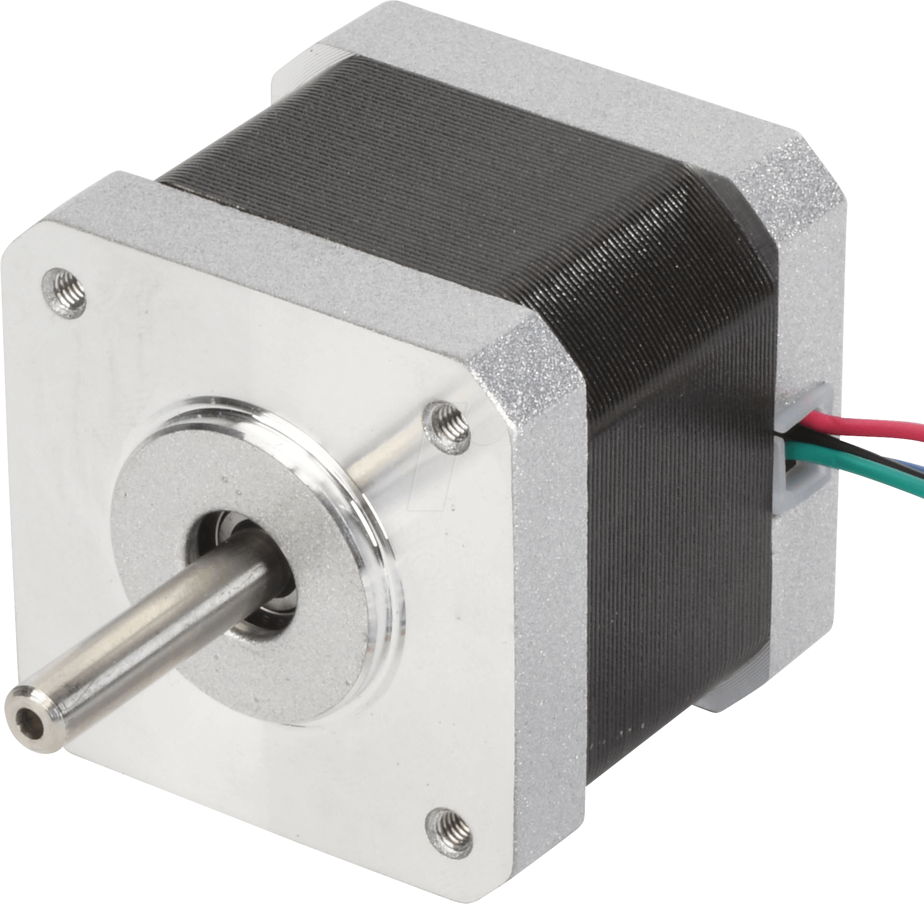
Stepper motor
Stepper motor is a brushless DC motor that rotates in steps. This is very useful because it can be precisely positioned without any feedback sensor, which represents an open-loop controller. The stepper motor consists of a rotor that is generally a permanent magnet and it is surrounded by the windings of the stator. As we activate the windings step by step in a particular order and let a current flow through them they will magnetize the stator and make electromagnetic poles respectively that will cause propulsion to the motor. So that’ the basic working principle of the stepper motors.
Jumper wires
Jumper cables is a smaller and more bendable corrugated cable which is used to connect antennas and other components to network cabling. Jumper wires are used for making connections between items on your breadboard and your Arduino's header pins.

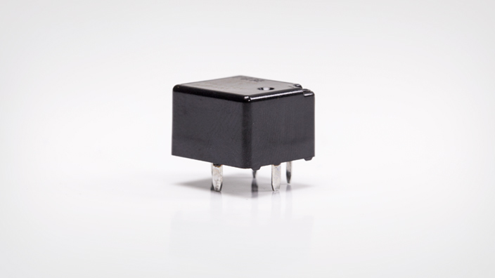
Relays
Relays are used to provide time delay functions. They are used to time the delay open and delay close of contacts. Relays are used to control high voltage circuits with the help of low voltage signals. Similarly they are used to control high current circuits with the help of low current signals.
IR sensor
Active infrared sensors both emit and detect infrared radiation. When an object comes close to the sensor, the infrared light from the LED reflects off of the object and is detected by the receiver. Active IR sensors act as proximity sensors, and they are commonly used in obstacle detection systems (such as in robots).

Existing solutions
Hand Gesture Controlled Robot using Arduino
In this project, we have designed a simple Hand Gesture Controlled Robot using Arduino. This Hand Gesture Controlled Robot is based on Arduino Nano, MPU6050, RF Transmitter-Receiver Pair and L293D Motor Driver. Even though the title says it as a Hand Gestured Controlled Robot, technically this robot is controlled by the tilt of the hand. https://www.electronicshub.org/hand-gesture-controlled-robot/
Gesture Controlled Robot with Wireless Camera Monitoring
An automated robot has been developed which works according to your hand gesture. The robot moves wirelessly according to palm gesture. The RF module is working on the frequency of 433 MHz and has a range of 50-80 meters. This robot can be upgraded to detect human life in earthquake and landslide by implementing the sensor accordingly. It can also be upgraded to bomb detecting robot as it has robotic arm it can also lift the bomb. GPS system can be added to the robot by the help of which its location can be tracked. https://www.ijert.org/research/gesture-controlled-robot-with-wireless-camera-monitoring-IJERTV6IS030419.pdf
Accelerometer Based Gesture Controlled Robot
In this project, a robotized robot has been produced which works as indicated by your hand gesture. The robot moves remotely as indicated by palm gesture. The RF module is chipping away at the recurrence of 433 MHz and has a scope of 50-80 meters. This robot can be moved up to identify human life in seismic tremor and avalanche by actualizing the sensor as needs be. It can likewise be moved up to bomb identifying robot as it has automated arm it can likewise lift the bomb. GPS framework can be added to the robot by the assistance of which its area can be followed. The significant favorable position of this framework over different frameworks is that it gives constant palm gesture acknowledgment, prompting a successful and common method for controlling robots. Extra preferred standpoint - numerous existing framework have utilized Bluetooth remote control which is supplanted by RF modules in this report, and because of which the range has been improved. http://www.ijetajournal.org/volume-5/issue-2/IJETA-V5I2P34.pdf
References
[1] Swetha N, Design and Implementation of Accelerometer based Robot motion and Speed control with Obstacle detection. IJSERT, volume 3, issue 2, pp 749-755, March2013.
[2] Rohan Sheoran et al., A Study of Hand Gesture Technique to Communicate with a Robot. IJERT, Vol. 4 Issue 01, pp. 12-13, January-2015.
[3] Bonny Varghese; B. Thilagavathi, Design and Wireless Control of Anthropomorphic Robotic Arm. 978-1-4799- 6818-3/15/$31.00©2015 IEEE.
[4] Diksha Goyal; Dr. S.P.S. Saini, Accelerometer Based Hand Gesture Controlled Wheelchair. IJET, volume 4, issue 2, pp 15-20, june-2013.
[5] Rahul Ranjan Singh et al., Wireless Controlled Robot Movement System Designed using Microcontroller. IJETT, volume 32, issue 5, pp 204-207, February 2016.
[6] Premangshu Chanda, PallabKanti Mukherjee, SubrataModak, AsokeNath, “Gesture Controlled Robot using Arduino and Android”, IJARCSSE, Volume 6, Issue 6, June 2016.
[7] P.V.Patil, M.B.Shete, T.M.Padalkar, “Wireless Hand Gesture Robot using Accelerometer, Volume: 03 Issue: 04 , Apr-2016.
[8] Saurabh A. Khajone, Dr. S. W. Mohod, V.M.Harne “Implementation of a Wireless Gesture Controlled Robotic Arm” in IJIRCCE Vol. 3, Issue 1, January 2015.
[9] Vivek Bhojak, Girish Kumar Solanki, Sonu Daultani “Gesture Controlled Mobile Robotic Arm Using Accelerometer” in IJIRSET Vol. 4, Issue 6, June 2015.
[10] SwarnaPrabha Jena, Sworaj Kumar Nayak, Saroj Kumar Sahoo, Sibu Ranjan Sahoo, Saraswata Dash, Sunil Kumar Sahoo ,“Accelerometer Based Gesture Controlled Robot Using Aurdino” IJESRT.
[11] Archika Setia, Surbhi Mittal, Padmini Nigam,Shalini Singh, Surendra Gangwar “Hand Gesture Recognition Based Robot Using Accelerometer Sensor” in IJAREEIE in Vol. 4, Issue 5, May 2015