Massbus Tape Controller (MT) - KS10FPGA/KS10FPGA GitHub Wiki
The Massbus Tape Controller is a tape system consisting of a TM03 Tape Controller/Formatter and one or more TU77 Tape Transports. A real TM03/TU77 system reads and writes tape data in the industry standard 1600 BPI Phase Encoded (PE) or 800 BPI Non-Return-to-Zero Inverted (NRZI) mode. None of the tape controllers or transports supported by the KS10 supported 6250 BPI Group Code Recording (GCR) density.
In this implementation, the tape system is similar to a client/server system where the FPGA-based tape controller (client) requests access to tape data (read and write) via a register interface. The Console Processor (server) reads and writes standard SIMH ".tap" files, translates the data between a stream of bytes on the tape and 36-bit PDP-10 words (with some metadata on the side), and makes the data available to the FPGA-based tape controller. In this case, metadata refers to tape objects like beginning-of-tape (BOT), end-of-tape (EOT), Tape Marks (TMs).
The SIMH ".tap" format doesn't really create a distinction between PE or NRZI tape formats. The tape controller implementation extends this abstraction in a way such that tapes are always appear to be read and written in the proper format.
Once the files are stored using the Console Processor's Linux filesystem, the ".tap" files can be stored anywhere on my network.
This SIMH Tape Format is documented at http://simh.trailing-edge.com/docs/simh_magtape.pdf. The translation between bytes on the tape and 36-bit (or 32-bit) PDP-10 data is documented in the TM03 Magnetic Tape Formatter Users Guide (EK-0TM03-UG-003).
Although the DSTUA and DSTUB Magtape diagnostics support the TM02 Tape Controller/Formatter and other tape transports besides the TU77, only the TM03 and the TU77 are supported currently.
I should probably mention that I have a pair of Kennedy 9400s that have the same "Pertec" interface as the TU77 - if I wanted the full experience watching of spinning tapes. Mercifully I don't have enough FPGA pins available on the DE-10 Nano to implement the Pertec interface without some kind of an IO expander because a Pertec interface requires a LOT of pins - a standard Pertec interface has two 50-pin connectors. It might be more interesting to think about designing a generic USB-to-Pertec adapter and just plugging that into KS10 FPGA system. It also could be used for other things.
At 170 pounds each, this is not near the top of my list of things to think about.
Each of the individual tape drives maintains some of its own state. In this context, that device state includes everything that would normally be associated with the physical tape drive. That device state includes the following registers:
MT Device Registers |
||||
Unibus Address |
Massbus Address |
TU Register Name |
R/W |
Register Description |
772440 |
0 |
R/W |
Control and Status Register #1 |
|
772442 |
- |
R/W |
Word Count Register |
|
772444 |
- |
R/W |
Bus Address Register |
|
772446 |
5 |
R/W |
Frame Count Register |
|
772450 |
- |
R |
Control and Status Register #2 |
|
772452 |
1 |
R |
Drive Status Register |
|
772454 |
2 |
R |
Error Register |
|
772456 |
4 |
R/W |
Attention Summary Register |
|
772460 |
7 |
R |
Check Character Register |
|
772462 |
- |
R/W |
Data Buffer Register |
|
772464 |
3 |
R/W |
Maintenance Register |
|
772466 |
6 |
R |
Drive Type Register |
|
772470 |
10 |
R |
Serial Number Register |
|
772472 |
11 |
R/W |
Tape Control Register |
|
Some of the bits in the MTCS1 Register are implemented in the RH11 Controller and some bits are implemented in the MT Device.

MT Control and Status Register #1 (MTCS1)
MT Control and Status Register #1 (MTCS1) – IO Address 772440 |
||||
Bit(s) |
Mnemonic |
R/W |
Description |
|
15 |
SC |
R |
See RH11 controller |
|
14 |
TRE |
R/W |
See RH11 controller |
|
13 |
CPE |
R |
See RH11 controller |
|
12 |
0 |
R |
See RH11 controller |
|
11 |
DVA |
R |
Drive available Always read as 1 |
|
10 |
PSEL |
R/W |
See RH11 controller |
|
9 |
A17 |
R/W |
See RH11 controller |
|
8 |
A16 |
R/W |
See RH11 controller |
|
7 |
RDY |
R |
See RH11 controller |
|
6 |
IE |
R/W |
See RH controller |
|
5-1 |
FUN[4:0] |
R/W |
Controller Function See the section entitled Simulator Functions for a description of these functions. FUN is only modified by writing to this field. FUN is NOT reset by
|
|
Code |
Description |
|||
00 |
No operation |
|||
01 |
Unload |
|||
02 |
Illegal function |
|||
03 |
Rewind |
|||
04 |
Drive Clear |
|||
05-07 |
Illegal function |
|||
010 |
Read-in Preset |
|||
011 |
Illegal function |
|||
012 |
Erase |
|||
013 |
Write tape mark |
|||
014 |
Space forward |
|||
015 |
Space Reverse |
|||
016-023 |
Illegal function |
|||
024 |
Write check forward |
|||
025-026 |
Illegal function |
|||
027 |
Write check reverse |
|||
030 |
Write forward |
|||
031-033 |
Illegal function |
|||
034 |
Read forward |
|||
035-036 |
Illegal function |
|||
037 |
Read reverse |
|||
0 |
GO |
R/W |
Execute function specified in FUN field. GO is asserted by writing a 1 with proper parity (Parity Test (MTCS2[PAT]) negated). GO is negated when the command completes. Technically on read-back, GO is Drive Ready (MTDS[DRY]) negated. GO is NOT reset by:
As noted above, the unit will not execute a command with incorrect parity. |
|
The Frame Count Register counts tape events.
When writing to tapes, the Frame Count register is loaded with the two's complement of the number of frames to be written. When the Frame Count register overflows to zero, the write operation terminates.
When reading or performing a write-check operation, the Frame Count need not be specified and is automatically reset to zero for those operation. When the read or write-check operation is complete, the Frame Count Register contains the number of frames read from tape.
This register is located on the M8909 Board and is on Sheet MBI 8 of the schematic.
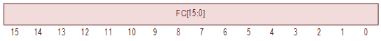
MT Frame Register (MTFC)
MT Frame Count Register (MTFC) – IO Address 772446 |
|||
Bit(s) |
Mnemonic |
R/W |
Description |
15-0 |
FC |
R/W |
Frame Count. The Frame Count Register operates as follows:
The contents of the Frame Count register may be read by the controller at any time; but the controller can only write into this register when the transport is not performing a space operation or data transfer operation (GO negated). Altered by writing. Cleared by TBD. |
This register reports the status of the tape drive.
This register is located on the M8933 Board and is on the schematic Sheet TCCM7.
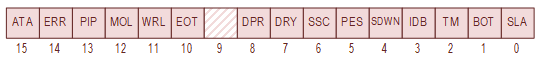
MT Drive Status Register (MTDS)
MT Drive Status Register (MTDS) – IO Address 772452 |
|||
Bit(s) |
Mnemonic |
R/W |
Description |
15 |
ATA |
R |
Attention Active ATA is asserted by the Tape Control Unit (TCU) under the following conditions:
ATA is negated under the following conditions:
|
14 |
ERR |
R |
Composite Error ERR is asserted by the Tape Control Unit (TCU)if any bits in MTER are asserted. This bit is combinatorially derived from those registers – clearing that bit in that register will negate ERR. Because every bit in the Error Register (MTER) is reset by any of the following methods, the ERR bit is also negated by:
When ERR is asserted , the only command that is accepted is the Drive Clear (MTCS2[FUN] = 4) command. |
13 |
PIP |
R |
Positioning in progress PIP is asserted by the Tape Control Unit (TCU) during a Space Operation and is asserted by the selected Tape Transport during a Rewind Operation. PIP is negated when the positioning command completes. |
12 |
MOL |
R |
Media On-line MOL is asserted by the selected Tape Transport. MOL is asserted when the selected slave is loaded and is on-line; otherwise negated. MOL is NOT affected by:
|
11 |
WRL |
R |
Write Lock WRL is asserted by the selected Tape Transport. On a 'real' tape drive, this would be asserted when a reel of tape without a write enable ring is loaded on the selected slave. In the KS10 FPGA, this is controlled by the MT Console Control Register which allows the operator to write protect the tape drive. WRL is NOT affected by
|
10 |
EOT |
R |
End of Tape EOT is asserted by the selected Tape Transport. EOT is asserted when the EOT marker is recognized during forward tape motion. EOT is negated when when any of the following occur:
|
9 |
- |
R |
Reserved Writes ignored. Always read as zero. |
8 |
DPR |
R |
Drive Present DPR is asserted by the Tape Control Unit (TCU). On a 'real' tape drive, this would be controlled by physically attaching the tape drive to the Massbus. In the KS10 FPGA, this is controlled by the MT Console Control Register which allows the operator to remove the tape drive. |
7 |
DRY |
R |
Drive Ready DRY is asserted by the selected Tape Control Unit (TCU). DRY is asserted at the completion of every command. DRY is negated at the start of every valid command. DRY is GO (MTCS1[GO]) negated. |
6 |
SSC |
R |
Slave Status Change SSC is asserted when any Tape Transport, selected or not, requires attention due to one of the following conditions:
Since SSC is a composite status of all slave devices, SSC is negated by:
Note: Issuing Drive Clear (MTCS2[FUN] = 4) command to the currently selected slave device will only negate SSC if the currently selected slave is the only slave that requires attention. |
5 |
PES |
R |
Phase Encoded Status
PES is asserted by the selected Tape Transport. PES emulates the PE/NRZI formatting state off the tape. Unlike a real tape, this state is only semi-persistent because it is not written on the tape. PES, however, is not affect by the Drive Clear (MTCS2[FUN] = 4) command or the the Massbus Init signal which is good enough to pass the diagnostics. PES is negated when the tape transport is taken off-line (or unloaded), or the tape transport is written in NRZI mode (MTTC[DEN] != 4) at BOT. PES is asserted when the tape transport is written in PE mode (MTTC[DEN] == 4) at BOT. PES is NOT affected by
Note: Writing to the tape file would create incompatabilities with SIMH which is undesirable. |
4 |
SDWN |
R |
Settle Down SDWN is asserted for 14 milliseconds by the selected Tape Transport whenever a motion command (forward, reverse, or rewind) is negated. SDWN is used by the tape transport to delay commands that cause tape motion irection changes until after the tape stops. This delay is elided if the tape motion direction of the current command is in the same direction as the previous command. SDWN is NOT affected by:
Note: The 14 millisecond period is defined (for the TU77) in the TU77 Magnetic Tape Transport Technical Manual Volume 2 (EK-2TUJ77-TM-002) on the bottom of Page 5-11. |
3 |
IDB |
R |
Identification Burst IDB is asserted by the selected Tape Transport. On a tape that is formatted for PE (see the PES bit), IDB is asserted during any Read Forward, Write Forward or Space Forward operation that begins at BOT. IDB is negated by:
|
2 |
TM |
R |
Tape Mark TM is asserted by the Tape Control Unit (TCU). TM is asserted when a tape mark is detected and remains set until the next tape motion operation is initiated. TM is negated by:
Note: The SIMH tape format has a different mechanism for encoding Tape Marks. |
1 |
BOT |
R |
Beginning of Tape BOT is asserted by the selected Tape Transport when passing BOT (Beginning of Tape) in the reverse direction. BOT is negated by the selected Tape Transport when passing BOT (Beginning of Tape) in the forward direction. MOL is NOT affected by:
|
0 |
SLA |
R |
Slave Attention SLA is asserted when the selected Tape Transport transitions from off-line to on-line. If interrupts are enabled, this raises an interrupt; since SLA asserts ATA, and ATA raises an interrupt. SLA is cleared by:
|
This register contains the error status of the addressed drive.
This register is located on the M8909 Board and is on the schematic Sheet MBI 10 and Sheet MBI 11.

MT Error Register (MTER)
MT Error Register (MTER) – IO Address 772454 |
|||
Bit(s) |
Mnemonic |
R/W |
Description |
15 |
COR/CRC |
R |
Correctable Data/CRC Error COR/CRC is set when:
COR/CRC is negated under the following conditions:
|
14 |
UNS |
R |
Unsafe UNS is asserted when:
UNS is negated under the following conditions:
|
13 |
OPI |
R |
Operation Incomplete OPI is asserted when:
OPI is negated under the following conditions:
|
12 |
DTE |
R |
Drive Timing Error DTE is not implemented. Writes ignored. Always read as zero. |
11 |
NEF |
R |
Non-Executable Function NEF is asserted when:
NEF is negated under the following conditions:
Aqny conditions that create a Non-Executable Function Error causes cause the function to not execute. |
10 |
CS/ITM |
R |
Correctable skew / Illegal Tape Mark CS/ITM is asserted when:
CS/ITM is negated under the following conditions:
|
9 |
FCE |
R |
Frame Count Error FCE is asserted when a space operation has terminated and the frame counter is not cleared. FCE is negated under the following conditions:
|
8 |
NSG |
R |
Non-Standard Gap NSG is asserted after a data transfer operation and when any tape characters are read while the read head is scanning the first half of the inter-record gap. NSG is negated under the following conditions:
|
7 |
PEF/LRC |
R |
PE Format Error/LRC This bit is asserted under the following conditions:
PEF/LRC is negated under the following conditions:
|
6 |
INC/VPE |
R |
In-correctable Data / Vertical Parity Error INC/VPE is asserted during an PE read operation when an uncorrectable error has occurred. (Not implemented) INC/VPE is asserted during an NRZI read operation when:
Note: A frame containing all zeros and with even parity has no flux changes on any channel and is indistinguishable from a gap on the tape. The tape transport 'fixes' this condition by flipping a data bit and applying even parity (i.e., two bits are set). INC/VPE is negated under the following conditions:
The SIMH tape format does not include parity and writing parity to the tape file would create incompatabilities with the SIMH which is undesirable. This feature is tested by DSTUA TST163. |
5 |
DPAR |
R |
Data Bus Parity Error DPAR is not implemented because it is not testable. DPAR is not tested by the DSTUA diagnostics when attached to an RH11. See note in DSTUA TST67. Writes ignored. Always read as 0. |
4 |
FMTE |
R |
Format Error FMTE is asserted when a data transfer function is issued with an unsupported format code (MTTC[FMT]). Any conditions that create a Format Error causes cause the transfer function to not execute. For a TM03, the only supported formats are (octal):
All other formats except those described above are unsupported and generate a Format Error. FMTE is negated under the following conditions:
This is tested by DSTUA TST72. |
3 |
CPAR |
R |
Control Bus Parity Error CPAR is asserted when Massbus device detects a parity error on the control bus. The KS10 FPGA does not implement parity on Massbus; but the Massbus devices do have a means to perform parity tests. In the KS10 FPGA, instead of this testing parity, this test mode simply forces parity errors. CPAR is asserted by asserting Parity Test on the RH11 (MTCS2[PAT]) and writing to one of the following registers:
CPAR is negated under the following conditions:
This is tested by DSTUA TST6. |
2 |
RMR |
R |
Register Modification Refused RMR is asserted when the controller attempts to write into any implemented tape transport register except the Maintenance Register (MTMR) or the Attention Summary Register (MTAS) when the GO bit is asserted. RMR is negated under the following conditions:
|
1 |
ILR |
R |
Illegal Register ILR is asserted when an attempt to read or write any register with an address higher than the MTTC register. ILR is negated under the following conditions:
|
0 |
ILF |
R |
Illegal Function ILF is asserted when and illegal function (MTCS2[FUN]) is selected and GO is asserted (MTCS1[GO]). The illegal functions are (octal, without "GO" bit): 02, 05, 06, 07, 011, 016, 017, 020, 021, 022, 023, 025, 026, 031, 032, 033, 035, and 036. ILF is negated under the following conditions:
|
The Attention Summary Pseudo Register allows the program to examine or modify the status of all tape drives in a single operation.

MT Attention Summary Register (MTAS)
MT Attention Summary (MTAS) – IO Address 772456 |
|||
Bit(s) |
Mnemonic |
R/W |
Description |
15-8 |
- |
R |
Writes ignored. Always read as zero. |
7 |
ATA7 |
R/W |
Attention Active on Tape 7 ATA7 reflects value of Tape 7's MTDS[ATA]. ATA7 is negated by writing 1 to Tape 7's MTDS[ATA]. |
6 |
ATA6 |
R/W |
Attention Active on Tape 6 ATA6 reflects value of Tape 6's MTDS[ATA]. ATA6 is negated by writing 1 to Tape 6's MTDS[ATA]. |
5 |
ATA5 |
R/W |
Attention Active on Tape 5 ATA5 reflects value of Tape 5's MTDS[ATA]. ATA5 is negated by writing 1 to Tape 5's MTDS[ATA]. |
4 |
ATA4 |
R/W |
Attention Active on Tape 4 ATA4 reflects value of Tape 4's MTDS[ATA]. ATA4 is negated by writing 1 to Tape 4's MTDS[ATA]. |
3 |
ATA3 |
R/W |
Attention Active on Tape 3 ATA3 reflects value of Tape 3's MTDS[ATA]. ATA3 is negated by writing 1 to Tape 3's MTDS[ATA]. |
2 |
ATA2 |
R/W |
Attention Active on Tape 2 ATA2 reflects value of Tape 2's MTDS[ATA]. ATA2 is negated by writing 1 to Tape 2's MTDS[ATA]. |
1 |
ATA1 |
R/W |
Attention Active on Tape 1 ATA1 reflects value of Tape 1's MTDS[ATA]. ATA1 is negated by writing 1 to Tape 1's MTDS[ATA]. |
0 |
ATA0 |
R/W |
Attention Active on Tape 0 ATA0 reflects value of Tape 0's MTDS[ATA]. ATA0 is negated by writing 1 to Tape 0's MTDS[ATA]. |
The check character register is a nine-bit, read-only register that permits the programmer to check the validity of a data transfer.
In NRZI mode, this register contains the CRCC for the operation.
In PE mode, at the end of a PE read operation, this register contains a "dead track" indication.
This register is located on the M8905 Board and is on the schematic Sheet MR4.

MT Character Check (MTCC)
MT Character Check (MTCC) – IO Address 772460 |
|||
Bit(s) |
Mnemonic |
R |
Description |
15-9 |
- |
R |
Reserved. Writes ignored. Always read as zero. |
8 |
CRCP |
R |
CRC Parity |
7-0 |
CRC |
R |
CRC Data |
The maintenance register is implemented as much as is required to pass diagnostic tests.
This register is located on the M8905 Board and is on the schematic Sheet MR5.

MT Maintenance Register (MTMR)
MT Maintenance Register (MTMR) – IO Address 772464 |
||||
Bit(s) |
Mnemonic |
R/W |
Description |
|
15-7 |
MDF[8:0] |
R/W |
Maintenance Data Field Contains the Longitudinal Redundancy Check Character (LRCC) of the last record after NRZI transfers.
Buffers the data generated during wraparound operations.
MDF is negated under the following conditions:
Note: The LRCC parity is reported in the low order bit of this register (MDF[0]).
|
|
6 |
SWC2 |
R |
Selected Slave Clock Writes ignored The SWC2 clock is generated by the tape transport and depends on the tape speed. The clock rate of the SWC2 bit is:
The clock dividers listed above are illustrated in the TM03 Technical Manual, in Figure 4-30. This is tested by DSTUA TST104. The clock frequencies listed
above are consistent with the values in the
|
|
5 |
MC |
R/W |
Maintenance Clock If the GO bit is asserted and the Maintenance Opcode is one of the following:
Then the MC bit toggles each time a write to the Maintenance Register (MTMR) is performed. Else, if the GO bit is asserted and the Maintenance Opcode is WRP0 (MTMR[MOP] = 03), the MC bit changes state after each read strobe occurs. MC is negated under the following conditions:
|
|
4-1 |
MOP[3:0] |
R/W |
Maintenance Opcode When the Tape Control Unit is in Maintenance Mode (MTMR[MM] = 1), this register controls the type of maintenance action to be performed. MOP is negated under the following conditions:
|
|
Opcode |
Remarks |
|||
00 |
No OP Executing this opcode has no effect on the system. |
|||
01 |
IRD Interchange Read |
|||
02 |
MREP Even Parity When this bit is set and data is sent from the Tape Controller to the RH11, the RH11 will indicate Massbus Data Bus Parity Errors (MTCS2[DPE] = 1) on all data bus (NPR) transfers and/or will indicate Massbus Control Bus Parity Errors (MTCS1[CPE] = 1) on all control bus transfers (register reads). Note: The KS10 FPGA does not implement parity. Merely setting this bit causes CPE and DPE failures under the conditions described above. This is sufficient to pass the DSTUA parity tests. |
|||
03 |
WRP0 Data Wraparound, Global. |
|||
04 |
WRP1 Data Wraparound, Partial. |
|||
05 |
WRP2 Data Wraparound, Formatter Write |
|||
06 |
WRP3 Data Wraparound, Formatter Read |
|||
07 |
CROCC Cripple Reception of OCC |
|||
010 |
ILCC1 In NRZI mode, suppress CRC check. In PE mode, suppress detection of data in logical track 1. |
|||
011 |
ITM12 In NRZI mode, set Bit-5 of tape data. In PE mode, suppress detection of data in logical track 1 and 2. |
|||
012 |
MMEOR Maintenance Mode End of Record. |
|||
013 |
INCPRE Invert Bit-1 of preamble and postamble in PE mode. |
|||
0 |
MM |
R/W |
Maintenance Mode When MM is asserted, the Tape Control Unit enters a maintenance mode. MM is negated under the following conditions:
|
|
This register indicates the type of tape drive that is connected to the controller.
This register is located on the M8933 Board and is on the schematic Sheet TCCM7.
The information in the table below was extracted from the DSTUA diagnostic.

MT Drive Type Register (MTDT)
RP Drive Type Register (RPDT) – IO Address 776726 |
||||
Bit(s) |
Mnemonic |
R/W |
Drive |
Register Contents |
15 |
NSA |
R |
All |
Not Sector Addressed Writes Ignored. Always read as 1. |
14 |
TAP |
R |
All |
Tape Transport Writes Ignored. Always read as 1. |
13 |
MOH |
R |
All |
Moving Head Writes Ignored. Always read as 0. |
12 |
7CH |
R |
All |
7 Channel Generally tape controller like the TM02/TM03 supported both 7-track and 9-track tape transports - the only significant difference between the two is the type of head. The tape transports indicates to the controller the type of drive by asserting (or negating) the "7CH" wire which is indicated by this status bit. This design only supports 9-track devices simply because the PDP-10 SIMH tape file format stores data in 8-bit bytes. Vertical Odd Parity (the 9th bit) is not supported by SIMH because the tape file is assumed to be loss-less. Writes Ignored. 7CH is read as 0. I don't know if mixing 7-track and 9-track devices on a single controller was supported or not. Probably not. You can mix TU16s and TE16s on the same salve bus; but, you cannot mix TU16s and TU45s on the same slave bus. |
11 |
DRQ |
R |
All |
Drive Request Required. Writes Ignored. Always negated to indicate a single port device. |
10 |
SPR |
R |
All |
Slave Present Writes Ignored. SPR is asserted after the transport is powered-up and the selection code has been written to the Tape Control Register (MTTC[SS]) register; otherwise negated. |
9-6 |
- |
R |
All |
Reserved Writes Ignored. Always read as 0. |
5 |
FMT |
R |
All |
Formatter Type Writes Ignored. This bit is asserted for a TM03 and negated for a TM02. |
4 |
- |
R |
All |
Reserved Writes Ignored. Always read as 0. |
3-0 |
DT |
R |
Drive Type |
|
DT |
Tape Unit Type |
|||
010 |
Unselected slave |
|||
011 |
TU16 |
|||
012 |
TU45 |
|||
013 |
TU16/TE16 |
|||
014 |
TU77 |
|||
015 |
Unknown |
|||
016 |
Unknown |
|||
017 |
Unknown |
|||
The MTSN register reports the Serial Number of the tape drive. The Serial Number is hardwired to the tape drive number. The values implemented in the FPGA are the same values that SIMH uses.
This register is located on the M8908 Board (single sheet).
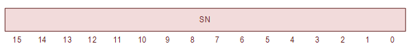
MT Serial Number Register (MTSN)
MT Serial Number Register (MTSN) – IO Address 772470 |
||||
Bit(s) |
Mnemonic |
R/W |
Drive |
Register Contents |
15-0 |
SN |
R |
0 |
000031 |
1 |
000032 |
|||
2 |
000033 |
|||
3 |
000034 |
|||
4 |
000035 |
|||
5 |
000036 |
|||
6 |
000037 |
|||
7 |
000040 |
|||
This register is located on the M8905 Board and is on the schematic Sheet MR6.

MT Tape Control Register (MTTC)
MT Tape Control Register (MTTC) – IO Address 772472 |
||||
Bit(s) |
Mnemonic |
R/W |
Description |
|
15 |
ACCL |
R |
Acceleration Writes ignored. The ACCL bit is asserted when the tape transport is getting up to speed or not moving. ACCL is asserted under the following conditions:
The ACCL bit is negated approximately 0.28 seconds after a Read command or Write command is initiated. In the TM03, the ACCL is negated after 16384 clock cycles the 800 BPI clock (60 KHz). |
|
14 |
FCS |
R |
Frame Count Status FCS is asserted when data is written into the Frame Count FCS is negated when any of the following occur:
|
|
13 |
SAC |
R |
Slave Access Change SAC is asserted when the Slave Select (MTTC[SS]) is modified. SAC is negated "on the next drive set pulse" - Writes ignored. |
|
12 |
EAODTE |
R/W |
Enable Abort On Data Transfer Errors EAODTE is modified by writing. EAODTE is negate when ... When asserted, EAODTE aborts read and write operations
|
|
11 |
- |
R/W |
Reserved Does nothing. Altered by writes. |
|
10-8 |
DEN[2:0] |
R/W |
Density Select DEN is modified by writes. DEN is NOT cleared by:
|
|
DEN[2:0] |
Description |
|||
0 |
200 BPI NRZI (TM02/TE16/TU16). 800 BPI NRZI (TM03). |
|||
1 |
556 BPI NRZI (TM02/TE16/TU16). 800 BPI NRZI (TM03). |
|||
2 |
800 BPI NRZI (TM02/TE16/TU16). 800 BPI NRZI (TM03). |
|||
3 |
800 BPI NRZI. |
|||
4 |
1600 BPI PE. |
|||
5 |
Unknown. |
|||
6 |
Unknown. |
|||
7 |
Unknown. |
|||
|
It looks to me (I could be wrong...) that only DEN[2] selects between 800 BPI NRZI and 1600 BPI PE density with this configuration of boards - the two LSBs (DEN[1:0]) are ignored. See notes regarding the description of the density initialization associated with the Preset function. |
||||
7-4 |
FMT[3:0] |
R/W |
Format Select FMT is modified by writes. FMT is NOT cleared by:
Apparently the TM02/TM03 supported multiple "Bit Fiddler" boards depending on the processor and tape transport. This section describes the M8915-YA which was used with the PDP-10 and the TU-77 Tape Transport. For additional information on Tape Formats, see: TU16/TM02 Tape Drive System Maintenance Manual - EK-TU16-MM-002 TM03 Magnetic Tape Formatter Technical Manual - EK-0TM03-TM-002 Revised July 1979. TOPS-10 Tape Processing Manual, AA-L412A-TB, July 1982, Section 6.1 entitled "DEC-Compatible Core Dump Mode (7- or 9-Track)" for tape formatting information. |
|
FMT[3:0] |
Description |
|||
0 |
PDP-10 Core Dump (TM02/TM03) On a 9-track tape, the PDP-10 Core Dump mode stores one 36-bit word of data in five 8-bit bytes. Note that the last frame is only half used (4-bits are always zero on reads and ignored on writes). In the TM02, this format requires the M-TBD Bit Fiddler board. In the TM03, this format requires the M8915 or M8915-YA Bit Fiddler board. |
|||
1 |
PDP-10 Seven Track (TM02 only) 6x 6-bit characters. In the TM02, this format requires the M8914 Bit Fiddler board. In the TM03, this format is not supported. Because the KS10 FPGA only supports the TM03, this format is not supported. |
|||
2 |
PDP-10 ASCII (TM02 only) In the TM02, this format requires the M8914 Bit Fiddler board. In the TM03, this format is not supported. Because the KS10 FPGA only supports the TM03, this format is not supported. |
|||
3 |
PDP-10 Compatibility (TM02/TM03) On a 9-track tape, the PDP-10 ASCII (8-bit) mode stores 32-bit data in four 8-bit bytes. On reads, the contents of the 4 LSBs of 36-bit word are undefined. The 4 LSBs either contain zeroes or copies of the parity bits depending on the tape drive and/or tape formatter. On writes, the contents of the 4 LSBs of 36-bit word are ignored and are not written to tape. In the TM02, this format requires the M8914 Bit Fiddler board. In the TM03, this format requires the M8915 or M8915-YA Bit Fiddler board. |
|||
4 |
Reserved |
|||
5 |
Reserved |
|||
6 |
Reserved |
|||
7 |
Reserved |
|||
010 |
Reserved |
|||
011 |
Reserved |
|||
012 |
Reserved |
|||
013 |
Reserved |
|||
014 |
PDP-11 Normal 2x 8-bit characters. In the TM02, this format is not supported. In the TM03, this format requires the M8906 Bit Fiddler board. In PDP-10 applications, this mode is not supported although it does not raise a Format Error (MTER[FMTE]) when selected. The Format Error is tested by DSTUA TST72. |
|||
015 |
PDP-11 Core Dump 4x 4-bit characters. Not supported. |
|||
016 |
PDP-15 Normal 2x 8-bit characters. This format requires the M8906 Bit Fiddler board. In PDP-10 applications, this mode is not supported although it does not raise a Format Error (MTER[FMTE]) when selected. The Format Error is tested by DSTUA TST72. |
|||
017 |
Reserved |
|||
3 |
EVPAR |
R/W |
Tape Parity When asserted in NRZI mode, even parity will be written When negated in NRZI mode, odd parity will be written Odd parity is always used in PE mode. EVPAR is modified by writing. EVPAR is negated by TBD. |
|
2-0 |
SS[2:0] |
R/W |
Slave Select Specifies the unit number of the tape transport. Modified by writing. SS[2:0] is NOT cleared by:
|
|
The TM02/TM03/TU77 can execute the following commands:
<tr>
  <td><p align="center">027</p></td>
  <td><p align="center">Write Check Reverse</p></td>
  <td>
    <p>At the start of the Write Check Reverse operation, the contents
      of the Frame Count Register is set to zero.
    </p>
    <p>The Write Check Reverse operation does a word-by-word comparison
      between the contents of memory and the data read from tape when
      the tape is moving in the backward direction (towards BOT).
      The status registers are updated during the operation as follows:
      <ul>
        <li>The Frame Counter is incremented for every byte read from
          tape.
        </li>
        <li>The Word Counter is incremented by two for every word
          compared with memory.
        </li>
        <li>The Base Address is decremented by two for every word
          compared with memory.
        </li>
      </ul>
    </p>
    <p>Note: the number of bytes per word varies depending on the
      selected tape format and is usually either 4 bytes-per-word
      or 5 bytes-per-word.
    </p>
    <p>The Write Check Reverse operation terminates when any of the
      following conditions exist:
      <ol>
        <li>A Tape Mark is detected. In that case, assert Tape Mark
          (MTDS[TM] = 1) and position the file just before the
          tape mark, or
        </li>
        <li>An beginning-of-file is detected. In that case, assert
          Beginning-of-Tape(MTDS[BOT] = 1) and position the file at
          the beginning-of-file, or
        </li>
        <li>The Frame Count Register (MTFC) increments to zero, or</li>
        <li>The Word Count Register (MTWC) increments to zero.</li>
      </ol>
    </p>
    <p>When completed, the Write Check Reverse function asserts
      Drive Ready (MTDS[DRY] = 1) and the Frame Count Register
      contains the number of bytes (frames) read from the tape.
    </p>
    <p>If a mismatch is detected, a Write Check Error is asserted
      (MTCS2[WCE] = 1).
    </p>
    <p>Note: as far as the tape transport is concerned, a Write Check
      Reverse operation is identical to a Read Reverse operation.
    </p>
  </td>
</tr>
<tr>
  <td><p align="center">030</p></td>
  <td><p align="center">Write Forward</p></td>
  <td>
    <p>The Write Forward operation reads data from memory and
      transfers the data to the Tape File while moving the tape in
      the forward direction (towards EOT). The status registers are
      updated during the operation as follows:
      <ul>
        <li>The Frame Counter is incremented for every byte written
          from tape.
        </li>
        <li>The Word Counter is incremented by two for every word
          written to memory.
        </li>
        <li>The Base Address is incremented by two for every word written
          to memory.
        </li>
      </ul>
    </p>
    <p>Note: the number of bytes per word varies depending on the
      selected tape format and is usually  either 4 bytes-per-word
      or 5 bytes-per-word.
    </p>
    <p>The Read Forward operation terminates when any of the
      following conditions exist:
      <ol>
        <li>A Tape Mark is detected. In that case, assert Tape Mark
          (MTDS[TM] = 1) and position the file just after the tape
          mark, or
        </li>
        <li>An end-of-file is detected. In that case, assert
          End-of-Tape (MTDS[EOT] = 1) and position the file at the
          end-of-file, or
        </li>
        <li>The Frame Count Register (MTFC) increments to zero, or</li>
        <li>The Word Count Register (MTWC) increments to zero.</li>
      </ol>
    </p>
    <p>When completed, the Write Forward function asserts Drive Ready
      (MTDS[DRY] = 1).
    </p>
  </td>
</tr>
<tr>
  <td><p align="center">034</p></td>
  <td><p align="center">Read Forward</p></td>
  <td>
    <p>At the start of the Read Forward operation, the contents of the
      Frame Count Register is set to zero.
    </p>
    <p>The Read Forward operation reads data from the Tape File
      and transfers the data to memory while moving the tape in the
      forward direction (towards EOT). The status registers are
      updated during the operation as follows:
      <ul>
        <li>The Frame Counter is incremented for every byte read
          from tape.
        </li>
        <li>The Word Counter is incremented by two for every word
          written to memory.
        </li>
        <li>The Base Address is incremented by two for every word
          written to memory.
        </li>
      </ul>
    </p>
    <p>Note: the number of bytes per word varies depending on the
      selected tape format and is usually either 4 bytes-per-word
      or 5 bytes-per-word.
    </p>
    <p>The Read Forward operation terminates when any of the following
      conditions exist:
      <ol>
        <li>A Tape Mark is detected. In that case, assert Tape Mark
          (MTDS[TM] = 1) and position the file just after the tape
          mark, or
        </li>
        <li>An end-of-file is detected. In that case, assert
          End-of-Tape (MTDS[EOT] = 1) and position the file at the
          end-of-file, or
        </li>
        <li>The Word Count Register (MTWC) increments to zero.</li>
      </ol>
    </p>
    <p>When completed, the Read Forward function asserts Drive Ready
      (MTDS[DRY] = 1) and the Frame Count Register contains the
      number of bytes (frames) read from the tape.
    </p>
  </td>
</tr>
<tr>
  <td><p align="center">037</p></td>
  <td><p align="center">Read Reverse</p></td>
  <td>
    <p>At the start of the Read Read operation, the contents of the
      Frame Count Register is set to zero.
    </p>
    <p>The Read Reverse operation reads data from the Tape File and
      transfers the data to memory while moving the tape in the reverse
      direction (toward BOT). The status registers are updated during
      the operation as follows:
      <ul>
        <li>The Frame Counter is incremented for every byte read
          from tape.
        </li>
        <li>The Word Counter is incremented by two for every word
          written to memory.
        </li>
      <li>The Base Address is decremented by two for every word
        written to memory.
      </li>
      </ul>
    </p>
    <p>Note: the number of bytes per word varies depending on the
      selected tape format and is usually either 4 bytes-per-word
      or 5 bytes-per-word.
    </p>
    <p>The Read Reverse operation terminates when any of the
      following conditions exist:
      <ol>
        <li>A Tape Mark is detected. In that case, assert Tape Mark
          (MTDS[TM] = 1) and position the file just before the
          tape mark, or
        </li>
        <li>A beginning-of-file is detected. In that case, assert
          Beginning-of-Tape (MTDS[BOT] = 1) and position the file
          at the beginning-of-file, or
        </li>
        <li>The Word Count Register (MTWC) increments to zero.</li>
      </ol>
    </p>
    <p>When completed, the Read Reverse function asserts Drive Ready
      (MTDS[DRY] = 1) and the Frame Count Register contains the number
      of bytes (frames) read from the tape.
    </p>
  </td>
</tr>
Command Function Codes |
||
Function Code |
Operation |
Description |
0 |
No Op |
Executing a No Op sets Drive Ready (MTDS[DRY]) immediately and has no other effect. |
01 |
Unload |
The unload function initiates a rewind on the selected transport, places it off-line, and unloads tape. The rewind operation is detailed below and is not repeated here. Note: Operator intervention is required to bring the slave back ONLINE. |
03 |
Rewind |
Rewinds to the Beginning-of-Tape (BOT) marker on selected transport. The rewind function operates as follows:
|
04 |
Drive Clear |
Resets the TM03 and the selected transport devices only. This does not affect unselected transport devices. The Drive Clear function clears GO (CSR1[GO]) immediately. |
010 |
Read-in Preset |
The Read-In Preset function does the following:
The rewind operation is detailed above and is not repeated here. Note: The documentation that describes the density select initialization for this command is confusing and misleading. The TM03 Users Guide says that read-in preset command should set the density to "800 bit/inch NRZI". Table 2-7 in the TM03 Users Guide shows that the correct register setting for "800 bit/inch NRZI" is 3 (not 2 as described above). Initializing this register to 3 will cause DSTUA TST106 to fail. Furthermore, the schematic M8905/MR6 clearly shows this register initialized to 2. It looks to me (I could be wrong...) that only DEN[2] selects between 800 BPI NRZI and 1600 BPI PE density with this configuration of boards. The two LSBs (DEN[1:0]) are ignored. Therefore a register setting of either 2 and 3 would select 800 BPI NRZI. Note also: Improper sequencing may cause spurious Unsafe indications (MTER[UNS]). This will occur when a Preset command is initiated which relies on the slave select change to slave 0 for the command to be valid. In this case, the slave change must occur before other errors are checked when the command is initiated. |
012 |
Erase |
The Erase Function erases approximately 3 inches of tape. When 800 BPI density is selected, 2400 bytes of data is erased. When 1600 BPI density is selected, 4800 bytes of data is erased. Starting at the current position, erase the amount of tape indicated by the specified length and density as described above. If the gap that is written overwrites an existing record, the following record is shortened appropriately. The tape is positioned after the gap. When completed, Erase does the following:
|
013 |
Write Tape Mark |
Writes a special tape mark meta-data character on the selected tape transport and positions the file just after the new tape mark.
When completed, Write Tape Mark does the following:
|
014 |
Space Forward |
The Space Forward command moves the tape forward (toward EOT) on the selected transport over the number of records specified by the Frame Count register. Each time a new record is detected, the Frame Counter is incremented. The Space Forward function terminates when any of the following conditions exist:
When a TM or EOT is detected, the contents of the Frame Count Register indicates the number of records that were spaced over. When completed, the Space Forward function:
|
015 |
Space Reverse |
Moves the tape reverse (toward BOT) on the selected transport over the number of records specified by the Frame Count register. Each time a new record is detected, the Frame Counter is incremented. The Space Reverse function terminates when any of the following conditions exist:
When a TM or BOT is detected, the contents of the Frame Count Register indicates the number of records that were spaced over. When completed, the Space Reverse function:
|
024 |
Write Check Forward |
At the start of the Write Check Forward operation, the contents of the Frame Count Register is set to zero. The Write Check Forward operation does a word-by-word comparison between the contents of memory and the data read from tape when the tape is moving in the forward direction (towards EOT). The status registers are updated during the operation as follows:
Note: the number of bytes per word varies depending on the selected tape format and is usually either 4 bytes-per-word or 5 bytes-per-word. The Write Check Forward operation terminates when any of the following conditions exist:
When completed, the Write Check Forward function asserts Drive Ready (MTDS[DRY] = 1) and the Frame Count Register contains the number of bytes (frames) read from the tape. If a mismatch is detected, a Write Check Error is asserted (MTCS2[WCE] = 1). Note: as far as the tape transport is concerned, a Write Check Forward operation is identical to a Read Forward operation. |
The MTDIR is a KS10 FPGA register that allows the MT hardware to interact with the console processor.
In the KS10 FPGA, the MT implementation is almost a client/server arrangement where the console processor performs all of the tape formatting and performs all of the file IO. The tape controller is implemented in the FPGA and makes file read/write requests of the console processor. The tape controller is the master. The console processor is slave.
Tape formatting includes all of the conversion between bytes-in-a-file and 36-bit words.
A general design rule, the bits in the MTDIR are either read-only or write-only. Some bits are listed as read/write but are really still exclusively read-only or write-only depending on the function being performed (or mode). This design eliminates the need for read/modify/write cycles and all the coherency issues that creates.
MT Data Interface Register (MTDIR) |
||||
Bit(s) |
Mnemonic |
R/W |
Description |
|
63 |
READ |
R |
Tape Read Mode READ is deprecated and should be ignored. |
|
62 |
STB |
R/W |
Strobe During read functions, the console processor will provide tape data from a file to the Tape Controller by asserting data onto the DATA bits and then asserting STB. Alternately STB and DATA can be asserted simultaneously in a single atomic 64-bit write operation, if that can be guaranteed. In this case, the Tape Controller automatically negates the STB signal once the data has been read. In read mode, the console processor cannot negate the STB signal once asserted. Note: Read functions include Read Forward, Read Reverse, Write Check Forward, and Write Check Reverse. During write functions, the Tape Controller will provide data to the console processor to write to a file, by asserting STB and asserting data on the DATA bits. When the console processor has read the data it should negate the STB signal. DATA should be ignored when STB is negated. In write mode, The console processor cannot assert STB. Note: The only write function is Write Forward. |
|
61 |
INIT |
R |
Initialize INIT is deprecated and should be ignored. |
|
60 |
READY |
R/W |
Ready The Tape Controller in the FPGA negates the READY bit to notify the console software to process a command. When the console software has completed the command, it asserts READY. Note: the console processor can only assert the READY bit. It cannot negate the READY bit. The MTDS[DRY] bit reflects the state of this bit. The MTCS1[GO] bit reflects the negated state of this bit. |
|
59 |
INCFC |
W |
Increment Frame Counter The console processor should assert INCFC to notify the tape controller to increment the Frame Counter. The tape controller automatically negates the INCFC bit when the Frame Counter has been incremented. Negating the INCFC bit has no effect. Always read as zero. |
|
58-56 |
SS[2:0] |
R |
Slave select Writes ignored. SS reflects the contents of the MTTC[SS] register. |
|
55-53 |
DEN[2:0] |
R |
Density Writes ignored. DEN reflects the contents of the MTTC[DEN] register. |
|
52-48 |
FUN[4:0] |
R |
Function Writes ignored. FUN reflects the contents of the MTCS1[FUN] register. |
|
47-44 |
FMT[3:0] |
R |
Format Writes ignored. FMT reflects the contents of the MTTC[FMT] register. |
|
43 |
WCZ |
R |
Word Count is Zero Writes ignored. WCZ is asserted when the contents of the Word Count Register is zero. |
|
42 |
FCZ |
W |
Frame Count is Zero Writes ignored. FCZ is asserted when the contents of the Frame Count Register is zero. |
|
41 |
SETBOT |
W |
Set Beginning-of-Tape When SETBOT is asserted, the Beginning-of-Tape indication (MTDS[BOT]) will be asserted. Negating the SETBOT bit has no effect. Always read as zero. |
|
40 |
CLRBOT |
W |
Clear Beginning-of-Tape When CLRBOT is asserted, the Beginning-of-Tape indication (MTDS[BOT]) will be negated. Negating the CLRBOT bit has no effect. Always read as zero. |
|
39 |
SETEOT |
W |
Set End-of-Tape When SETEOT is asserted, the End-of-Tape indication (MTDS[EOT]) will be asserted. Negating the SETEOT bit has no effect. Always read as zero. |
|
38 |
CLREOT |
W |
Clear End-of-Tape When CLREOT is asserted, the End-of-Tape indication (MTDS[EOT]) will be negated. Negating the CLREOT bit has no effect. Always read as zero. |
|
37 |
SETTM |
W |
Set Tape Mark When SETTM is asserted, the Tape Mark indication (MTDS[TM]) will be asserted. Negating the SETTM bit has no effect. Always read as zero. |
|
36 |
CLRTM |
W |
Clear Tape Mark When CLRTM is asserted, the Tape Mark indication (MTDS[TM]) will be negated. Negating the CLRTM bit has no effect. Always read as zero. |
|
35-0 |
DATA[0:35] |
R/W |
Tape Data See operation of the STB bit above for a description of how to read and write to the DATA bits. During read operations, DATA is write-only. During write operations, DATA is read-only. The console processor performs all of the tape formatting which involves translating bytes on the tape into 36-bit PDP-10 words and vice-versa. The console processor supports the same formats that the DEC TM03 supports. Note: There is an endian swap in this register. |
|
The following timing parameters are extracted from the DSTUA diagnostic and apply to the TM03 attached to a TU77 only. Where possible, the design behind the timing parameters is documented.
MT Timing Parameters |
|||
Parameter |
Tested |
Requirement |
|
TIMOPW |
TST74 |
OPI on write ... shall be greater than 7 seconds and less than 9 seconds (8 seconds nominal) |
|
TIMOPR |
TST74 |
OPI on write ... shall be greater than 7 seconds and less than 9 seconds (8 seconds nominal) |
|
TIMWAB |
TST123 |
Write Forward Startup Delay at BOT At BOT and when a Write Forward command is issued, the time between GO asserting and ACCL negating shall be greater than 49.3 ms and less than 55.6 ms (52.5 ms nominal). |
|
TIMWU |
TST123 |
Write Forward Shutdown Time at BOT At BOT and when a Write Forward command is issued, the time between the Frame Counter overflow and SDWN asserted shall be greater than 1.97 ms and less than 2.33 ms (2.15 ms nominal). |
|
TIMWE |
TST123 |
Write Forward Settledown Time at BOT At BOT and when a Write Forward command is issued, the time between the SDWN is asserted until SDWN is negated shall be greater than 8.93 ms and less than 18.8 ms (13.9 ms nominal). |
|
TIMWAN |
TST124 |
Write Forward Startup Delay not at BOT When not at BOT and when a Write Forward command is issued, the time between GO asserted and ACCL negating shall be greater than 2.96 ms and less than 3.44 ms (3.2 ms nominal). |
|
TIMRAB |
TST125 |
Read Forward Startup Delay at BOT At BOT and when a Read Forward command is issued, the time between GO asserted and ACCL negating shall be greater than 5.66 ms and less than 7.34 ms (6.5 ms nominal). |
|
TIMRFU |
TST125 |
Read Forward Shutdown Time at BOT At BOT and when a Read Forward command is issued, the time between GO asserted and ACCL negating shall be greater than 474 us and less than 800 us (636 us nominal). |
|
TIMRFE |
TST125 |
Read Forward Settledown Time at BOT At BOT and when a Read Forward command is issued, the time between the SDWN is asserted until SDWN is negated shall be greater than 8.10 ms and less than 18.9 ms (13.5 ms nominal). |
|
TIMRAN |
TST126 |
Read Forward Startup Delay not at BOT When not at BOT and when a Read Forward command is issued, the time between asserting GO and ACCL negating shall be greater than 475 us and less than 775 us (625 us nominal). |
|
TIMRRA |
TST127 |
Read Reverse Startup Delay not at BOT When not at BOT and when a Read Reverse command is issued, the time between asserting GO and ACCL negating shall be greater than 475 us and less than 775 us (625 us nominal). |
|
TIMRRU |
TST127 |
Read Reverse Shutdown Time not at BOT When not at BOT and when a Read Reverse command is issued, the time between when the final Frame Counter value is reached and when SDWN is asserted shall be greater than 427 us and less than 703 us (565 us nominal). |
|
TIMRRE |
TST127 |
Read Forward Settledown Time not at BOT When not at BOT and when a Read Reverse command is issued, the time between the SDWN is asserted until SDWN is negated shall be greater than 8.1 ms and less than 18.9 ms (13.5 ms nominal). |
|
TSTDFR |
TST130 |
Forward to Reverse Turn Around Time When a Read Reverse command follows a Write Forward command, the time between the Write Forward command asserting DRY and the Read Reverse command negating ACCL shall be greater than 9.47 ms and less than 19.4 ms (14.4 ms nominal). |
|
TIMDRF |
TST131 |
Reverse to forward Turn Around Time When a Read Forward command follows a Read Reverse command, the time between the Read Reverse command asserting DRY and the Read Forward command negating ACCL shall be greater than 9.57 ms and less than 19.4 ms (14.5 ms nominal). |
|
The console processor performs tape file IO operations for the FPGA-based Tape Controller in a manner that is compatible with the SIMH ".tap" file format.
There are some fundamental differences between how a tape drive stores information and how a tape file stores information on disk drive. The SIMH "*.tap" file format attempts to minimize those differences but some still exist. Some of these differences are described in the following sections.
The tape is defined to be at BOT when the file pointer is at the beginning of file; or when the value returned by ftell() is zero.
The Magtape has two notions of EOT: the logical EOT and the physical EOT.
The logical EOT is a sequence two tape marks and is purely a magtape storage convention. As such, the logical EOT is not relevant to this FPGA hardware design.
The physical EOT on a classic Magtape drive is a length reflecting tape near the end of the tape that is sensed by the tape transport drive. In this system where the Magtape is simulated using a file, the physical EOT is indicated on read forward operations at the end-of-file (EOF). When writes are performed, the end-of-file (and therefore physical EOT) can change without indication except when the file size becomes greater than the number of bytes that the tape can store. When this file size is exceeded, the physical EOT is indicated on both read and writes.
The number of bytes that the tape can store (bytes per tape) is a function of the length of the tape (in feet) and the recording density (in bytes per inch). Common tape lengths were 800 feet, 2400 feet, and 3600 feet. This system supports recording density of 800 bytes per inch and 1600 bytes per inch. For example, a 2400 foot tape formatted at 1600 BPI can store 46,080,000 bytes.
Write operations include Erase, Write Tape Mark, and Write Forward. Read forward operations include Space Forward, Write Check Forward, and Read Forward.
When the ".tap" file is opened, the file is validated for correctness. This ensures that there is a logical EOT before the physical EOT - and therefore EOT is known.
The console processor performs all of the formatting normally associated with the Bit Fiddler section of the TM03 formatter.
For now (and maybe forever...), only the TM03 functionality is implemented in the KS10 FPGA.
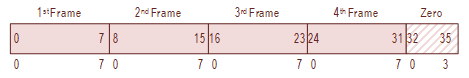
The following PDP-10 tape formats are supported by the TM02 and TM03:
On a 9-track tape transport, the PDP-10 core dump format stores one 36-bit word of data in five 8-bit frames (8 bit of data plus one bit of parity).
On writes, the 4 low-order bits of the last frame are set to zero. On reads, the 4 low-order bits of the last frame are ignored.
This tape format was supported by both the TM02 and TM03 and is supported by the KS10 FPGA.

PDP-10 Core Dump Format
On a 7-track tape transport, the PDP-10 core dump format stores one 36-bit word of data in six frames where each frame stores a 6 bits of data (plus one bit of parity).
This tape format was only supported by the TM02 tape control unit and was only supported when the tape TM02 was attached to a 7-track tape transport.
Because the KS10 FPGA only implements the TM03 tape control and 9 track tape transports, this tape format is not supported.

PDP-10 Seven Track Format
This format was also called "interchange" depending on the reference and was used for ANSI compliant ASCII interchange between the PDP-10 and 8-bit byte-oriented machines.
This format stores one 7-bit ASCII "byte" in each frame of the tape.
Bit 35 must be zero to conform to ANSI standards. Bit 35 (in a non-standard compliant use) is written into the high-order bit of the last frame of each word. The other high-order bits are set to zero on write operations. When the tape is read, all five high-order bits are ORed, and the result is stored in bit 35.
This format is only supported by the TM02 tape control unit. The KS10 FPGA only implements the TM03 and therefore this format is not implemented.

PDP-10 ASCII Format
This format is also sometimes called "compatibility", "compat", "normal", or "eight-bit" format depending on the reference.
This format is compatible with any machine that reads and writes 8-bit bytes and I believe generally replaced the PDP-10 ASCII mode format described above. The format transfers 32-bit words.
When a read operation is performed, four 8-bit frames are read into each 36-bit word (left justified) with the remaining four low-order bits of the word set to zero. When a write operation is performed, the 32 high-order bits of the 36-bit word are written into four 8-bit frames (plus parity). The four low-order bits are ignored.
This tape format was supported by both the TM03 and is supported by the KS10 FPGA.
PDP-10 Compatible Format
The TM03 formatter used by the PDP-10 also supported the PDP-11.
In PDP-10 applications, this mode is not supported although it does raise a Format Error (MTER[FMTE] asserted) when selected. The Format Error is tested by DSTUA TST72.
See MTTC[FMT[3:0]] and MTER[FMTE] bit descriptions.
The TM03 formatter used by the PDP-10 also supported the PDP-15.
In PDP-10 applications, this mode is not supported although it does raise a Format Error (MTER[FMTE] asserted) when selected. The Format Error is tested by DSTUA TST72.
See MTTC[FMT[3:0]] and MTER[FMTE] bit descriptions.
This section summarizes the results of executing the relevant diagnostic programs.
DECSYSTEM 2020 RH11-TM02/03-TU45/TU77 BASIC DEVICE DIAGNOSTIC (DSTUA)
VERSION 0.3, SV=0.3, CPU#=2020, MCV=130, MCO=470, HO=0, KASW=003740 000000

TTY SWITCH CONTROL ? - 0,S OR Y <CR> - Y

LH SWITCHES <# OR ?> - 0
RH SWITCHES <# OR ?> - 400000
SWITCHES = 000000 400000

MEMORY MAP =
FROM     TO          SIZE/K
00000000 03777777       1024

SPECIFY TM (3=TM03,2=TM02,CR WILL TEST ALL ON-LINE DRIVES)

CONFIGURATION:
RH11#  3772440
TM03#0  TU77 #'S:  0

NOTE: ANY TAPES MOUNTED WRITE-ENABLED MAY BE WRITTEN ON.

WHAT TEST (H<CR> FOR HELP): <CR>

BASIC TEST

BASIC TEST PART 1
TST1
TST2

NOW TESTING TM03#0 USING TU77 SLAVE #0 ***********
TST3
TST4
TST5
TST6
TST7
TST10
TST11
TST12
TST13
TST13A
TST13B
TST13C
TST13D
TST13E
The DSTUB diagnostics will run until it finds an EOT. I often shorten this test by loading a shorter tape; i.e., a tape this is shorter than 2400 feet.
DECSYSTEM 2020 RH11-TM02/03-TU16/TU45/TU77 RELIABILITY DIAGNOSTIC(DSTUB)
VERSION 0.5, SV=0.3, CPU#=2020, MCV=130, MCO=470, HO=0, KASW=003740 000000

TTY SWITCH CONTROL ? - 0,S OR Y <CR> - Y

LH SWITCHES <# OR ?> - 0
RH SWITCHES <# OR ?> - 400000
SWITCHES = 000000 400000

MEMORY MAP =
FROM     TO          SIZE/K
00000000 03777777       1024

SPECIFY TM (3=TM03,2=TM02,CR WILL TEST ALL ON-LINE DRIVES)

CONFIGURATION:
RH11#  3772440
TM03#0  TU77 #'S:  0
   SN= 0018.


NOTE: ANY TAPES MOUNTED WRITE-ENABLED MAY BE WRITTEN ON.

WHAT TEST (H<CR> FOR HELP):
TYPE NUMBER OF PROGRAM PASSES (DECIMAL) (CR=INFINITE): 1
TST2
1600BPI RELIABILITY TEST
TM03/TU77 0/0   SN= 0018.

TST3
800BPI RELIABILITY TEST

CURRENT TEST= 3;  CURRENT BUNCH= 1.;  STATISTICS:

TM03/TU77 0/0 IN 1600BPI MODE
        RECORDS*        SERS*   HERS*   BS/DERS NR OF WDS*
WRITE:  5106.           0.      0.      0.      10238195.
RD FWD: 5104.           0.      0.      0.      10238195.
RD REV: 5104.           0.      0.      0.      10238195.
NO DEAD TRKS

TM03/TU77 0/0 IN NRZI MODE
        RECORDS*        SERS*   HERS*   BS/DERS NR OF WDS*
WRITE:  2585.           0.      0.      0.      5121560.
RD FWD: 2583.           0.      0.      0.      5121560.
RD REV: 2583.           0.      0.      0.      5121560.

SMMON CMD -
The MT system is a work in progress.
The diagnostic status is summarized below:
                                   DIAGNOSTIC                                  Result
------------------------------------------------------------------------------ ------
DECSYSTEM 2020 RH11-TM02/03-TU45/TU77 BASIC DEVICE DIAGNOSTIC (DSTUA)            Fail
DECSYSTEM 2020 RH11-TM02/03-TU16/TU45/TU77 RELIABILITY DIAGNOSTIC (DSTUB)      Pass
Click on the underlined Pass/Fail issues links in the table above for more information regarding status.