DUP11 Bit Synchronous Serial Interface - KS10FPGA/KS10FPGA GitHub Wiki
The DUP11 Synchronous Serial Interface provides a relatively high speed (for the time) interface to other computers.
The DUP11 Verilog implementation is fully parameterized: the base IO address and the interrupt vector are controlled by module parameters. Two DUP11s could be instantiated and attached to the IO Bus Bridge (UBA) adapters - however only one DUP11 is currently instantiated in the code.
DUP11 Configuration |
||||
Device |
UBA |
Interrupt |
Interrupt |
Base |
DUP11 #1 |
UBA 3 |
5 |
000560 |
760300 |
DUP11 #2 |
UBA 3 |
5 |
000600 |
760310 |
A summary of DUP11 registers is shown below:
DUP11 Register Summary |
||||
IO Addr |
IO Addr |
Register |
Access |
Register Description |
760300 |
760310 |
RXCSR |
Byte (R/W) |
Receiver Control/Status Register |
760302 |
760312 |
RXDBUF |
Word (R/O) |
Receiver Buffer Register |
760302 |
760312 |
PARCSR |
Word (W/O) |
Parameter Control/Status Register |
760304 |
760314 |
TXCSR |
Byte (R/W) |
Transmitter Control/Status Register |
760306 |
760316 |
TXDBUF |
Byte (R/W) |
Transmitter Data Buffer |
The DUP11 supports several synchronous serial protocols in hardware. This slightly lessens the CPU loading required to process these data streams.

SDLC/ADCCP Protocol
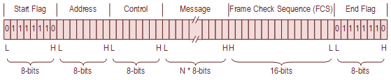
DDCMP/BISYNC Protocol
This section provides programming and implementation details of the DUP11 registers.
The RXCSR provides most of the control and status applicable to the serial receiver operation, including the modem control signals.
The RXCSR is read/write and is word- and byte-addressable.
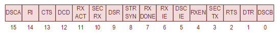
Receiver Control/Status Register (RXCSR)
|
DUP11 RX Control/Status Register (RXCSR) – IO Address 760300 |
|||
Bit(s) |
Mnemonic |
R/W |
Description |
15 |
DSCA |
R |
Data Set Change A This bit is set when:
This bit is cleared by:
If the Data Set Change interrupt is enabled (RXCSR[DSCIE] = 1), the assertion of this bit causes an interrupt to the receiver vector. Writes ignored. Note: Configuration W5 is normally not installed. The manual entitled DUP11Bit Synchronous Interface Maintenance Manual (EK-DUP11-MM-003) says that "A positive transition on the Ring line greater than 10 ms" will set DSCA. This statement is misleading if not incorrect. Refer to Figure 4-31 for the schematic of the Ring Indication Line. This circuit detects both rising and falling edges. The DSDUA diagnostic Test 61 will fail if the circuit only detects rising edges. The 10 millisecond debounce is not implemented. |
14 |
RI |
R |
Ring Indication This bit reflects the state of the modem Ring Indication modem signal. Writes ignored. |
13 |
CTS |
R |
Clear To Send This bit reflects the state of the Clear to Send modem signal. Writes ignored. |
12 |
DCD |
R |
Data Carrier Detect This bit reflects the state of the Data Carrier Detect modem signal. Writes ignored. |
11 |
RXACT |
R |
Receiver Active This bit is set when:
This bit is cleared by:
Writes ignored. |
10 |
SECRX |
R |
Secondary Received Data This bit would normally reflect the state of the Secondary Received Data modem signal. The secondary receive data function is not implemented. This bit is looped-back to the SECTX bit, therefore this bit reflects the state of the RXCSR[SECTX] bit. Writes ignored. |
9 |
DSR |
R |
Data Set Ready This bit reflects the state of the Data Set Ready modem signal. Writes ignored. |
8 |
STRSYN |
R/W |
Strip Sync Once the receiver is synchronized, any received characters that match the Sync Character (PARCSR[SYNADR]) and are contiguous with the sync sequence are not presented to the program (i.e., the receiver done (RXCSR[RXDONE] will not be set). This strips extra sync characters that may be present in the sync sequence. This bit is set by writing a 1. This bit is cleared by:
Note: This bit is only used with the DDCMP and BISYNC protocols (PARCSR[DECMD] = 1). Setting this bit in SDLC and ADCCP mode (PARCSR[DECMD] = 0) will disable the receiver. |
7 |
RXDONE |
R |
Receive Done. This bit indicates that data is available in the Receiver Buffer Register (RXDBUF[RXDBUF]). This bit is set when:
This bit is cleared by:
Receiver Done is NOT set when a the Address Character is received and the receiver is configured for Secondary Station Mode (PARCSR[SSM] = 1). Writes ignored. |
6 |
RXIE |
R/W |
Receiver Interrupt Enable When this bit is asserted, an receiver interrupt is generated when the receiver has data (RXCSR[RXDONE] = 1). This bit is set by writing a 1. This bit is cleared by:
|
5 |
DSCIE |
R/W |
Data Set Change Interrupt Enable When enabled causes a receiver interrupt request when the Data Set Change A (RXCSR[DSCA]) bit is set. This bit is set by writing a 1. This bit is cleared by:
|
4 |
RXEN |
R/W |
Receiver Enable When initially set, this causes the receiver to search for the synchronization sequence irrespective of mode. Once synchronization has been attained, clearing this bit will asynchronously (to the receiver clock) reset the receiver state. This bit is set by writing a 1. This bit is cleared by:
|
3 |
SECTX |
R/W |
Secondary Transmitted Data Secondary mode is selected by asserting PARCSR[SECMODE]. The secondary transmit data function is not implemented. It simply loops back to the Secondary Receiver Input. This bit is set by writing a ‘1’. This bit is cleared by:
Note: Configuration W3 is normally installed. |
2 |
RTS |
R/W |
Request to Send This bit asserts the RTS signal to the Modem. This bit is set by writing a ‘1’. This bit is cleared by:
Note: Configuration W3 is normally installed. |
1 |
DTR |
R/W |
Data Terminal Ready This bit asserts the DTR signal to the Modem. This bit is set by writing a ‘1’. This bit is cleared by:
Note: Configuration W3 is normally installed. |
0 |
DSCB |
R |
Data Set Change B This bit is set when:
This bit is cleared by:
Writes ignored. Note: Configuration W6 is normally installed. |
The upper byte of this register contains the remainder of the receiver status information, including the receiver error flags. The lower bytes provides access to the Receiver Buffer Register which contains the received data.
The RXDBUF is read-only and word-addressable.
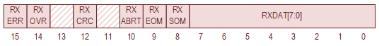
Received Data Buffer (RXDBUF)
|
DUP11 RX Data Buffer Register (RXDBUF) – IO Address 760302 |
|||
Bit(s) |
Mnemonic |
R/W |
Description |
15 |
RXERR |
R |
Receiver Error This bit is set when any of the following bits are set:
Clearing the errors above will clear this error. |
14 |
RXOVRE |
R |
Receiver Overrun Error An overrun occurs data is present (RXCSR[RXDONE] = 1) but the data is not read from the Receiver Data Buffer (RXDBUF[RXDAT]) before the next character is received and stored in the Receiver Data Buffer. This bit is set when a receiver overrun occurs and data is lost. This bit is cleared by:
Note: When set, this bit is only set until the next transfer from the receiver shift register to the Receiver Data Register (RXDBUF[RXDAT]). |
13 |
- |
R |
Reserved Writes ignored. Always read as zero. |
12 |
RXCRCE |
R |
Receiver CRC Error This bit is set when:
This bit is cleared by:
Note: When set, this bit is only set until the next transfer from the receiver shift register to the Receiver Data Register (RXDBUF[RXDAT]). |
11 |
- |
R |
Reserved Writes ignored. Always read as zero. |
10 |
RXABRT |
R |
Receiver Abort Error This bit is set in SDLC/ADCCP Mode (PARCSR[DECMD] = 1) when an SDLC Abort Sequence is received. This bit is cleared by:
This bit is only asserted in SDLC/ADCCP mode (PARCSR[DECMD] = 0) – it is never asserted in DDCMP/ BISYNC mode. Note: An SDLC Abort Sequence is defined as a sequence of eight contiguous ones. When an Abort Sequence is received, the receiver state is reset. When an abort is detected, RXDONE is asserted, and RXACT if negated. |
9 |
RXEOM |
R |
Receiver End of Message This bit is set in SDLC/ADCCP mode (PARCSR[DECMD] = 1), and receiver synchronization was previously attained, and an End Flag character is received. This bit is cleared by:
This bit is only asserted in SDLC/ADCCP mode (PARCSR[DECMD] = 0) – it is never asserted in DDCMP/BISYNC mode. When the End Flag is received, the contents of the Receiver Data Register (RXDBUF[RXDAT]) are undefined. Note: When set, this bit is only set until the next transfer from the receiver shift register to the Receiver Data Register (RXDBUF[RXDAT]). |
8 |
RXSOM |
R |
Receiver Start of Message This bit is set when:
This bit is cleared by:
This bit is only asserted in SDLC/ADCCP mode (PARCSR[DECMD] = 0) – it is never asserted in DDCMP/ BISYNC mode In Primary Station Mode, the Address Character is treated like part of the synchronization process – if the address is incorrect, the hardware keeps searching for a flag character followed by the correct station address. In Secondary Station Mode, the Address character is reported to the KS10. |
7-0 |
RXDAT |
R |
Receiver Data This field is set when by data is transferred to this receiver from the receiver shift register. This bit is cleared by:
|
The high byte of this register contains the bits that control the DEC Mode, secondary address mode, and enable or disable the CRC logic.
The low byte (bits 0-7) contains the 8-bit secondary station address that is used only when the secondary mode is enabled in the SDLC protocol. In DEC Mode operation, this register contains the SYNC character.
The Parameter Control/Status Register is word accessible only and is write-only

Parameter Control/Status Register (PARCSR)
|
DUP11 Param Control/Status Register (PARCSR) - IO Address 760302 |
|||
Bit(s) |
Mnemonic |
R/W |
Description |
15 |
DECMD |
W |
DEC Mode This controls the operation of the receiver and transmitter protocol state machines. When negated, the device supports SDLC and ADCCP protocols. When asserted the device supports DDCMP and BISYNC protocols. This bit is set by writing a ‘1’. This bit is cleared by:
|
14-13 |
- |
W |
Reserved Writes ignored. Always read as zero. |
12 |
SSM |
R/W |
Secondary Station Mode This bit is used in SLDC mode only. It is cleared in DDCMP and BISYNC modes. If set, only messages with the correct secondary address are presented to the program. If cleared, all characters after the last flag character are presented to the program. This bit is set by writing a ‘1’. This bit is cleared by:
|
11-10 |
- |
W |
Reserved Writes ignored. Always read as zero. |
9 |
CRCI |
W |
CRC Inhibit This bit modifies the operation of the receiver and transmitter state machine to inhibit the transmission of the CRC and the testing of the received CRC. This bit is set by writing a ‘1’. This bit is cleared by:
|
8 |
- |
W |
Reserved Writes ignored. Always read as zero. |
7:0 |
SYNADR |
R/W |
DDCMP Sync Character / Secondary Station Address When in DDCMP Mode (PARCSR[DECMD] = 1), this parameter is set to the SYN character and is used by the receiver to synchronize to the data stream. In SDLC/ADCCP mode and Secondary station mode, this parameter is loaded with the Secondary Station Address which immediately follows the Flag Character. If the character after Flag Character matches the contents of this field, then receiver synchronization occurs. If it mismatches, the receiver continues to search for a proper synchronization sequence and the message is dropped. This bit is cleared by:
Note: This parameter is not used by the transmitter. |
The TXCSR provides most of the control and status applicable to the transmitter operation; it also contains the bits to control the DUP11 operation in maintenance mode.
The TXCSR is read/write and is byte addressable.

Transmitter Control/Status Register (TXCSR)
DUP11 TX Control/Status Register (TXCSR) - IO Address 760304 |
||||
Bit(s) |
Mnemonic |
R/W |
Description |
|
15 |
TXDLE |
R |
Data Late Error This bit indicates that the transmitter serial port has underrun and there is no data available for the next character. This bit is set when no data is available (TXCSR[TXDONE] = 1). This status is sampled in the middle of the last bit of the character being sent. This bit is cleared by:
When this occurs in SDLC mode, the transmitter sends an abort character and terminates the transmission. When this occurs in DDCMP mode, the transmitter goes to a “Mark Hold” state, where the transmitter sends a sequence of ones until a new message is started. Writes ignored. |
|
14 |
MDO |
R |
Maintenance Data Out When configured for Internal Maintenance Mode (TXCSR[MSEL] = 2), this bit reflects the transmitter output. This is used by the diagnostic program to test the transmitter. Writes ignored. |
|
13 |
MCO |
R/W |
Maintenance Clock Out When configured for Internal Maintenance Mode (TXCSR[MSEL] = 2), this bit provides the transmitter and receiver clock and allows the diagnostic software to single-step the transmitter and receiver hardware. A 0-to-1 transition of this bit causes the transmitter to transfer one bit of information to the serial line. A 1-to-0 transition of this bit causes the receiver to shift the contents of the receiver shift register and sample the serial input line. This bit is set by writing a 1. This bit is cleared by:
|
|
12-11 |
MSEL |
R/W |
Maintenance Mode Select. These bits are set by writing ones. This bit is cleared by:
The various modes are detailed below
|
|
0 |
User Mode (USER)
This is the normal operating mode. In this mode, there is no loopback, internal or external, and the modem provides the clock signal for the DUP11 serial interface. |
|||
1 |
System Test Mode (SYS) This mode performs an external loopback. A modem is not required. In this mode, the clock signal for the DUP11 serial interface which is normally provided by the modem is generated internally by the DUP11. The modem control signals and transmit/ received data signals must be looped back by an external device. In a DEC KS10 system, the “H325 Turn Around Connector” provided this loopback mechanism. The description of this bit in Table 3-5 of the document entitled “DUP11 Bit Synchronous Interface User's Manual (EK-DUP11-0P-002)” is incorrect. Similarly, the description of this bit in the document entitled “DUP11 Bit Synchronous Interface Maintenance Manual (EK-DUP11-MM-003)” is incorrect. It is correctly detailed in Table 4-2 of the latter document. |
|||
2 |
Internal Maintenance Mode (INT) In this mode, the KS10 bit-bangs the serial clock which allows the KS10 to single-step data through both the serial transmitter and receiver interfaces. The modem control signals and transmit/ received data signals must be looped back by an external device. In a DEC KS10 system, the “H325 Turn Around Connector” provided this loopback mechanism. The description of this bit in Table 3-5 of the document entitled “DUP11 Bit Synchronous Interface User's Manual (EK-DUP11-0P-002)” is incorrect. Similarly, the description of this bit in the document entitled “DUP11 Bit Synchronous Interface Maintenance Manual (EK-DUP11-MM-003)” is incorrect. It is correctly detailed in Table 4-2 of the latter document. |
|||
3 |
External Maintenance Mode (EXT) This mode performs an internal loopback. In this mode, all of the loopback, clock and data, is performed onboard the DUP11. It cannot check external interfaces. The description of this bit in Table 3-5 of the document entitled “DUP11 Bit Synchronous Interface User's Manual (EK-DUP11-0P-002)” is incorrect. Similarly, the description of this bit in the document entitled “DUP11 Bit Synchronous Interface Maintenance Manual (EK-DUP11-MM-003)” is incorrect. It is correctly detailed in Table 4-2 of the latter document. |
|||
10 |
MDI |
R/W |
Maintenance Data In When configured for Internal Maintenance Mode (TXCSR[MSEL] = 2), this bit can be used as the receiver serial input. When this bit is set and the Maintenance Clock Out (TXCSR[MCO]) bit makes a 1-to-0 transition, a logical 1 is transferred into the receiver shift register. This bit is set by writing a 1. This bit is cleared by:
|
|
9 |
TXACT |
R |
Transmitter Active This bit is set when the transmitter begins sending data on the serial output. This bit is cleared by:
|
|
8 |
INIT |
W |
Device Reset (or Controller Clear). This bit does the following:
This bit is read as zero |
|
7 |
TXDONE |
R |
Transmitter Done This bit reports the state of the transmitter. This bit is set when:
This bit is cleared by:
Writes ignored. |
|
6 |
TXIE |
R/W |
Transmitter Interrupt Enable This bit is set by writing a 1. This bit is cleared by:
|
|
5 |
- |
R |
Reserved Writes ignored. Always read as zero. |
|
4 |
SEND |
R/W |
Send This bit should remain set until the TXEOM bit is loaded into the TXDBUF. If this bit is cleared at any other time, the current character is finished and the transmitter output goes to a mark hold state. If SEND is cleared while TXEOM is still asserted, the current character being transmitted is completed. Following this character, and depending on the protocol being used, any necessary CRC and/ or control characters are transmitted. This bit is set by writing a 1. This bit is cleared by:
|
|
3 |
HDX |
R/W |
Half-Duplex Mode Not implemented. This bit is set by writing a 1. This bit is cleared by:
|
|
2-0 |
- |
R |
Reserved Writes ignored. Always read as zero. |
|
The high byte of this register contains the transmitter control and status information, plus two status bits from the Receiver CRC Register and Transmitter CRC Register.
The low byte provides the transmitter data buffer that contains the information to be transmitted.
The TXDBUF is read/write and is byte addressable.

Transmitter Data Buffer (TXDBUF)
|
– DUP11 TX Data Buffer (TXDBUF) - IO Address 760306 |
|||
Bit(s) |
Mnemonic |
R/W |
Description |
15 |
- |
R |
Reserved Writes ignored. Always read as zero. |
14 |
RXCRC |
R |
Receiver CRC Register LSB. This bit contains the LSB of the Receiver CRC Register when configured Internal Maintenance Mode (TXCSR[MSEL] = 3). In all other modes, this register is zero. |
13 |
- |
R |
Reserved Writes ignored. Always read as zero. |
12 |
TXCRC |
R |
Transmitter CRC Register LSB. This bit contains the LSB of the Transmitter CRC Register when configured Internal Maintenance Mode (TXCSR[MSEL] = 3). In all other modes, this register is zero. |
11 |
MNTT |
R |
Maintenance Timer This bit is used as a timing reference for the diagnostics. The diagnostic appears to use this signal as a delay reference for the modem control signals. For example, the Ring Indication Line has a 10 millisecond debounce period. The diagnostic changes the state of the line and waits, using this timer, before checking the input state |
10 |
- |
R/W |
Transmit Abort When this bit is asserted, an Abort Sequence is transmitted after the current character sent, if a character is in-process. The SEND bit should be asserted when the Abort Sequence is transmitted. TXDONE is set at the end of the Abort Sequence. This bit is set by writing a 1. This bit is cleared by:
Note: In the DUP11 implementation, an Abort Sequence is a sequence of more 8 contiguous ones. |
9 |
TXEOM |
R/W |
Transmit End of Message Asserting this bit causes the contents of the CRC register to be transmitted after the current character. This bit is set by writing a 1. This bit is cleared by:
|
8 |
TXSOM |
R/W |
Transmit Start of Message. In SDLC Mode, asserting this bit causes a Flag Character to be sent. If the TXDBUF[TXSOM] bit is still asserted at the end of the character, another Flag Character will be sent. At the end of each flag character, the CRC register is reset. The Flag Character is generated by the USRT transmitter – it does not come from the TXDBUF[TXDAT] register. In DDCMP Mode, asserting this bit causes the CRC register to be initialized at the end of each character that is transmitted. This is the only difference between data and SYN characters as they both come from the TXDBUF[TXDAT] register. This bit is set by writing a 1. This bit is cleared by:
|
7-0 |
TXDAT |
R/W |
Transmit Data These bits are set by writing a 1. These bits are cleared by:
|
A transcript of the DUP11 Diagnostic Tests is included below:
SMMON CMD - DSDUA

DSDUA DECSYSTEM 2020 DUP-11 DIAGNOSTICS
VERSION 0.2, SV=0.3, CPU#=2020, MCV=130, MCO=470, HO=0, KASW=003740 000000

TTY SWITCH CONTROL ? - 0,S OR Y  - 0
SWITCHES = 000000 000000


'COMMAND MODE' IS INDICATED WHEN THE PROGRAM TYPES
 AN "*" AT THE LEFT SIDE OF THE TERMINAL. TO RE-START
THE ONCE ONLY DIALOG FROM 'COMMAND MODE' TYPE "&".

IS THE DUP-11 UNIT #1 OR #2 ?1

DO YOU WANT A MAP OF THE DUP-11 STATUS ? Y OR N  - Y

IS THE H325 TURN AROUND CONNECTER IN PLACE ? Y OR N  - Y
* INITIAL DUP STATUS MAP *

UNIBUS ADAPTER IS #03
DUP11 IS          #01


********************
RXCSR :000000 041002
RXDBUF:000000 000000
TXCSR :000000 000200
TXDBUF:000000 000000
UASTAT:000000 002000


TYPE ? TO GET FORMAT ON (TERMINAL), OR % TO GET SUMMARY OF CONTROLLER
TESTS, (SEE TEXT FILE FOR CONTROL OF SUMMARY OUTPUT DEVICE SELECTION.)

*%


TEST.1-- *REGISTER ACCESS TEST*
TEST.2-- *TXCSR REGISTER R/W TEST*
TEST.3-- *TXCSR HI-BYTE TEST*
TEST.4-- *TXCSR LO-BYTE TEST*
TEST.5-- *TXCSR CLEAR TEST (MRESET)*
TEST.6-- *TXCSR CLEAR TEST (UBINIT)*
TEST.7-- *RXCSR REGISTER R/W TEST*
TEST.10-- *RXCSR HI-BYTE TEST*
TEST.11-- *RXCSR LO-BYTE TEST*
TEST.12-- *RXCSR CLEAR TEST (MRESET)*
TEST.13-- *RXCSR CLEAR TEST (UBINIT)*
TEST.14-- *TXDBUF REGISTER R/W TEST*
TEST.15-- *TXDBUF CLEAR TEST (MRESET)*
TEST.16-- *TXDBUF CLEAR TEST (UBINIT)*
TEST.17-- *PARCSR/RXDBUF CLEAR TEST (MRESET)*
TEST.20-- *PARCSR/RXDBUF CLEAR TEST (UBINIT)*
TEST.21-- *PARCSR REGISTER WRITE/RXDBUF READ TEST*
TEST.22-- *TXCSR REGISTER READ ONLY TEST*
TEST.23-- *RXCSR REGISTER READ ONLY TEST*
TEST.24-- *TXCSR 0'S DISTURB TEST*
TEST.25-- *TXDBUF 0'S DISTURB TEST*
TEST.26-- *RXCSR 0'S DISTURB TEST*
TEST.27-- *RXDBUF 0'S DISTURB TEST*
TEST.30-- *SYSTEM TEST MODE/FREE RUNNING CLOCK TEST*
TEST.31-- *INTERNAL MAINT MODE/STATIC XMITTER FCNS (SEND-TXDONE-TSOM)*
TEST.32-- *INTERNAL MAINT MODE/STATIC XMITTER FCNS (TXDBUF-TXACT-
           TSOM-TRANSMITTED DATA-TXDONE)*
TEST.33-- *INTERNAL MAINT MODE/IDLE FLAGS TEST*
TEST.34-- *INTERNAL MAINT MODE/BASIC XMITTER TEST*
TEST.35-- *INTERNAL MAINT MODE/ABORT SEQUENCE TEST*
TEST.36-- *MAINT MODE/DATA UNDER-RUN TEST*
TEST.37-- *INTERNAL MAINT MODE/'SEND//TEOM' INTERACTION TEST
           (WITHOUT BIT STUFF)*
TEST.40-- *INTERNAL MAINT MODE/'SEND/TEOM' INTERACTION TEST
           (WITH BIT STUFF)*
TEST.41-- *INTERNAL MAINT MODE/'DATA UNDER-RUN'TEST*
TEST.42-- *INTERNAL MAINT MODE/'TSOM//TEOM'TEST*
TEST.43--*INTERNAL MAINT MODE (TEST OF THE BCC OPERATION
          USING CRC.CCITT FOR THE POLYNOMIAL)TEST*
TEST.44-- *INTERNAL MAINT MODE/RCVR EN-RCVR ACTIVE-RSOM
           (PRIMARY MODE) TEST*
TEST.45-- *INTERNAL MAINT MODE/RCVR EN-RCVR ACTIVE-RSOM
           (SECONDARY MODE) TEST*
TEST.46-- *INTERNAL MAINT MODE/'REOMM//RXDONE' (PRIMARY MODE) TEST*
TEST.47-- *INTERNAL MAINT MODE/'REOM//RXDONE'
           (SHARED ZERO BIT IN FLAG-PRIMARY MODE)TEST*
TEST.50--*INTERNAL MAINT MODE/'REOM//RXDONE '(IN SECONDARY MODE) TEST *
TEST.51--*INTERNAL MAINT MODE /'ABORT//RXDONE' (PRIMARY MODE) TEST*
TEST.52--*INTERNAL MAINTNANCE MODE /'ABORT//RXDONE'
          (SECONDARY MODE) TEST*
TEST.53--*INTERNAL MAINTNANCE MODE /'RXDERR/OVRRUN' (PRIMARY MODE)TEST*
TEST.54--*INTERNAL MAINTNANCE MODE/'RXDERR//OVRRUN'(SECONDARY MODE)TEST*
TEST.55--*INTERNAL MAINT MODE/ 'TXDBUF//RXDBUF'
           (SPECIFIC DATA PATERNS THRU RECIEVER IN PRIMARY MODE) TEST*
TEST.56--*SYSTEM TEST MODE (VERIFY THAT THE DEVICE WILL WORK WITH ALL
          POSSIBLE SECONDARY STATION ADDRESSES)TEST*
TEST.57--*INTERNAL MAINTNANCE MODE(TEST OF THE BCC OPERATION USING
          CRC.CCITT FOR THE POLYNOMIAL)TEST*
TEST.60--*INTERNAL MAINT MODE (IDLE STATE) TEST*
TEST.61--*EXTERNAL MAINT MODE 'DTR//DSR!RING' TEST*
TEST.62--*EXTERNAL MAINT MODE 'RTS//CTS!CARDET' TEST*
TEST.63--*EXTERNAL MAINT MODE 'STD//SRD' TEST*
TEST.64--*EXTERNAL MAINT MODE (RXCSR) TEST*
TEST.65--*SYSTEM TEST MODE(TRANSMITTER INTERRUPT)TEST*
TEST.66--*SYSTEM TEST MODE(TRANSMITER INTERRUPT)TEST*
TEST.67--*EXTERNAL MAINT MODE(RECIEVER INTERRUPT)TEST*
TEST.70--*SYSTEM TEST MODE(RECIEVER INTERRUPT TEST)*
TEST.71--*SYSTEM TEST MODE(RECIEVER INTERRUPT) TEST*
TEST.72--*SYSTEM TEST MODE(INTERRUPTS)TEST*
TEST.73--*SYSTEM TEST MODE(INTERRUPT)TEST*
TEST.74--*SYSTEM TEST MODE 'RXDONE//INTERRUPT' TEST*
TEST.75--*SYSTEM TEST MODE 'TABORT//INTERRUPT' TEST*


*A
STARTING *BASIC REGISTER TESTING*
*ACCESSING REGISTER:000003760300
*ACCESSING REGISTER:000003760302
*ACCESSING REGISTER:000003760304
*ACCESSING REGISTER:000003760306
STARTING *REGISTER DISTURB TESTING*
STARTING *INTERNAL MAINTENANCE MODE (TRANSMITTER) TESTING*
STARTING *INTERNAL MAINTENANCE MODE (RECEIVER) TESTING*
STARTING *SYSTEM & EXTERNAL MAINTNANCE* TESTING
END PASS 1.
The DUP11 Controller implementation is rather new and somewhat untested. The KS10 diagnostics only tests the DUP11 in SDLC mode; it does not perform any testing in DDCMP mode. The documentation for DDCMP mode is somewhat limited.
The diagnostic status is summarized below:
                           DIAGNOSTIC                              Result
------------------------------------------------------------------ ------
DSDUAB0 DECSYSTEM 2020 DUP-11 DIAGNOSTICS                          Pass