Zigbee Color Control Light On TBS2 - Jim-tech/IoT-Developer-Boot-Camp GitHub Wiki
Table of Contents
We used to have a reference design about color-control-light which is RD-0098-0401, but it's deprecated now. All the documents about this reference design can't be found on Silicon Labs' official website.
This example is a Zigbee color-control-light example based on Thunder Board Sense 2. It demonstrates controlling RGB color using Zigbee.
Below is the hardware layout of Thunder Board Sense 2:

Gecko SDK Suite 2.7.
- 2 pcs Thunder Board Sense 2
Form a Zigbee network on the light, and then join the switch into the network.
-
Create a ZigbeeMinimal project, name it with "Z3ColorLight" and select the "BRD4166A" (the board type for Thunder Board Sense 2) as the board.
-
In "Zigbee Stack" tab, set the device type to "Coordinator or Router".
-
In "ZCL Clusters" tab, select endpoint 1, then in "Zigbee device type" field, change it to HA devices-->HA Color Dimmable Light.
-
In cluster "Color Control", enable the following attributes:
- remaining time
- color mode, default value set to 1.
-
Set the default value, so that the RGB LEDs will be turned on by default.
- In cluster On/Off, set default value of on/off attribute to
0x01. - In cluster Level Control, set default value of current level attribute to
0xC8.
- In cluster On/Off, set default value of on/off attribute to
-
Enable the following plugins:
- On/Off Server Cluster
- Level Control Server Cluster
- Color Control Cluster Server
- Buld PWM Driver
- Led Rgb Pwm
- Network Creator
- Network Creator Security
- Source Route Library
- Identify Cluster
- Find and Bind Target
-
In plugin "Serial", in the properties, select USART0, change the Flow control mode to No flow control, then save.
-
In plugin "Bulb PWN Driver", select BULBPWM_COLOR, check the Enable, and set CC0, CC1, CC2 to true.

Then select **TIMER0**, disable the timer channel **CC0**, **CC1**, **CC2** as TIMER0 will not be used in this example.
Select **TIMER1**, configure the pins for **CC0**, **CC1**, **CC2** to **PD11**, **PD12**, **PD13** respectively.
-
In "Callbacks" tab, enable the following callbacks:
- emberAfMainInitCallback
- emberAfStackStatusCallback
- emberAfPluginNetworkSteeringCompleteCallback
- emberAfHalButtonIsrCallback
-
Add two custom event:
- Event
buttonEventControland its handlerbuttonEventHandler - Event
closeNetworkEventControland its handlercloseNetworkEventHandler
- Event
-
Save and generate the project.
-
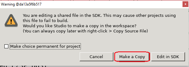
We need to modify two source files of the SDK because the the corresponding function is not supported on Thunder Board Sense 2. As this source files are linked into the SDK, there will be a pop-up warning windows like below. If you see it, please always select "Make a Copy".
A. Modify source file `bulb-pwm-driver/EFR32/bulb-pwm-driver-efr32.c`:026 //#define BULB_PWM_USING_TIMER0 Comment this line as TIMER0 is used by the stack 027 028 #define BULB_PWM_WHITE_TIMER BSP_BULBPWM_TIMER 029 #define BULB_PWM_WHITE_CHANNEL 0 030 #define BULB_PWM_LOWTEMP_TIMER BSP_BULBPWM_TIMER 031 #define BULB_PWM_LOWTEMP_CHANNEL 1 032 #define BULB_PWM_STATUS_TIMER BSP_BULBPWM_TIMER 033 #define BULB_PWM_STATUS_CHANNEL 2
B. Modify source file
led-rgb-pwm/led-rgb-pwm.c:224 static void driveWRGB(uint16_t white, uint16_t red, uint16_t green, uint16_t blue) 225 { 226 //halBulbPwmDriverSetPwmLevel(white, BULB_PWM_WHITE); -- comment this line 227 halBulbPwmDriverSetPwmLevel(red, BULB_PWM_RED); 228 halBulbPwmDriverSetPwmLevel(green, BULB_PWM_GREEN); 229 halBulbPwmDriverSetPwmLevel(blue, BULB_PWM_BLUE); 230 } 630 /** @brief Called during blinking behavior telling the bulb implementation to turn the bulb on. 631 * 632 * @appusage Should be implemented by an application layer configuration 633 * plugin. 634 * 635 */ 636 void halBulbPwmDriverBlinkOnCallback(void) 637 { 638 //halBulbPwmDriverSetPwmLevel(halBulbPwmDriverTicksPerPeriod(), BULB_PWM_WHITE); -- comment this line 639 halBulbPwmDriverSetPwmLevel(halBulbPwmDriverTicksPerPeriod(), BULB_PWM_RED); 640 halBulbPwmDriverSetPwmLevel(halBulbPwmDriverTicksPerPeriod(), BULB_PWM_GREEN); 641 halBulbPwmDriverSetPwmLevel(halBulbPwmDriverTicksPerPeriod(), BULB_PWM_BLUE); 642 } 643 644 /** @brief Called during blinking behavior telling the bulb implementation to turn the bulb off. 645 * 646 * @appusage Should be implemented by an application layer configuration 647 * plugin. 648 * 649 */ 650 void halBulbPwmDriverBlinkOffCallback(void) 651 { 652 //halBulbPwmDriverSetPwmLevel(OFF_TICKS, BULB_PWM_WHITE); -- comment this line 653 halBulbPwmDriverSetPwmLevel(OFF_TICKS, BULB_PWM_RED); 654 halBulbPwmDriverSetPwmLevel(OFF_TICKS, BULB_PWM_GREEN); 655 halBulbPwmDriverSetPwmLevel(OFF_TICKS, BULB_PWM_BLUE); 656 }
-
Implement the callback file
Z3ColorLight_callbacks.c. Refer to the file in the project. -
Save and build.
- Create a ZigbeeMinimal project, name it with "Z3ColorSwitch" and select the "BRD4166A" (the board type for Thunder Board Sense 2) as the board.
- In "ZCL Clusters" tab, select endpoint 1, then in "Zigbee device type" field, change it to HA devices-->HA Color Dimmable Switch.
- Enable the following plugins:
- Find and Bind Initiator
- Enable the following callbacks:
- emberAfStackStatusCallback
- emberAfPluginNetworkSteeringCompleteCallback
- emberAfHalButtonIsrCallback
- emberAfPluginFindAndBindInitiatorCompleteCallback
- Add a custom event
buttonEventControland its handlerbuttonEventHandler. - Save, generate.
- Implement the callbacks in the file
Z3ColorSwitch_callbacks.cand build. Refer to the file in the exported project. - Save and build.
- Flash the light and switch program into the two boards.
- On the console of the Light, press button0 to create a network. When its done, the LED (The LED in the middle of the board, not the RGB LED) will turn orange.
- On the switch, press button0 to start joining. This must be done when the LED of the light is orange. If it's red other than orange, press button1 of the light and then press button0 of the switch. If the switch joined successfully, the LED of the switch will turn orange.
- Press button1 of the switch to change the color.
This example can be used on any parts. Below are the steps of porting it to other part:
- Import the .sls file into Simplicity Studio
- Open the .isc file of each project, turn to "General" tab, hit button "Edit Architecture", then select the board and part.
 Home |
 ![]() Zigbee |
Zigbee | ![]() Bluetooth |
Bluetooth | ![]() ZWave |
ZWave | ![]() Proprietary |
Proprietary | ![]() Thread |
Thread | ![]() Matter |
Matter | ![]() Hardware |
Hardware | ![]() Common
Common
All resources of this repository are released under license CC BY-NC-ND 4.0 