RF Test Guide - Jim-tech/IoT-Developer-Boot-Camp GitHub Wiki
English | 中文
Table of Contents
As described in AN1048, the product should pass the regulation and be certified if it will be sold in that region. Usually there is no big problem if the customer comply with the design rules of Silicon Labs' reference design. But some times the customer want to customize its design to fit the final application, it needs doing some pre-tests based on customer design to pass the regulation. If some test items can not pass the regulation, then some tuning and calibration steps will be required. In the following contents, it will introduce RF regulatory certification regions in brief firstly, then some tuning, calibration, and testing methods will be described in detail for customer reference.
Silicon Labs has many products such as SOC chips, SiP modules, and PCB modules. And the products support main sub-GHz bands(169MHz, 434MHz, 868MHz and 915MHz) and 2.4GHz frequency band. These different products and frequency bands almost comply to regulations from any region in the world.
There are many region regulations such as CE (Europe), FCC (USA), ISED (Canada), MIC (Japan), KC (South Korea) and other regions.
And there are some test houses provide certification service for the regions as following:

For the certification activities, you can directly contact the region authorities:

In general, there are RF, EMC and Safety separate categories to be certified in these regions, RF certification test is mainly introduced here. For more information about regulatory certification, please refer to AN1048.
A number of antenna types (e.g. printed inverted-F antenna) can inherently be matched to the desired input impedance (typically, 50-ohm single-ended) without using any external tuning component. However, the board size, plastic enclosures, metal shielding, and components in close proximity to the antenna can detune the antenna performance. Thus it leads to higher radiation harmonics, poor radation power, and degraded sensitivity. In order to get an optimized radiation performance, the antenna might require tuning that can be realized in two ways:
- Dimension changes in the antenna layout structure;
- Applying external tuning components.
Typically it prefer to the solution that the layout modification is not required in a custom design. To accomplish this, Silicon Labs generally recommends to use SMD placeholders as external antenna tuning components, which the suggested external antenna matching structure is a 3-element PI network as following picture shows. You can achieve a good match using as a maximum of two elements (with one series and one shunt component) of the PI network. Any unknown passive impedance can be matched to 50 ohms by using this PI network, since all L, C, L-C, C-L combinations can be realized on it, and therefore any de-tuning effect can be compensated out.
Note that every implementation of an antenna design might require different combinations of inductors and capacitors.
The recommended 3-element PI network for external antenna matching purposes is here:
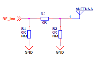
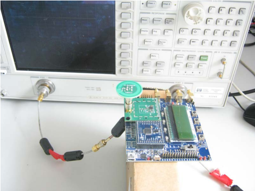
It is recommended to add a pi network for antenna matching as shown in Figure 1. Finding appropriate values for the antenna matching components should be considered an iterative task. Usually it use a Vector Network Analyser (VNA) to tune and measure the antenna matching network as following figure shows.

The following matching steps and tricks are proposed:
-
Calibrate your VNA for a frequency range larger than the intended bandwidth of the antenna.
-
Connect an RF coaxial cable to the RF line (for instance by soldering a pigtail to the line). Connect the RF coaxial cable to a VNA to measure the reflection coefficient, S11, looking into the antenna through the matching network.
a. Be sure to have a good connection to the ground plane to get the best electrical performance and the highest mechanical robustness during the measurement.
b. Make sure to route the pigtail towards the center of the PCB and then perpendicularly away from the PCB at the center point. This will limit the effect of the cable on the measured data as much as possible. The following picture shows the detail:
-
Start with no components on the antenna network shown in Figure 1.
a. The shunt components are not mounted.
b. The series component is not mounted.
-
Using port extension function in the VNA to move the reference point to the footprint of R1 and R2. This is achieved when the locus of the S-parameters in the Smith chart on the VNA have assembled in a point at the right edge of the Smith chart. The following picture shows detail:

-
Mount a 0 Ω resistor at R2 in Figure 1.
-
Measure reflection coefficient of the center frequency of interest (the frequency half way between the lowest frequency and the highest frequency of the interesting band).
-
Using an online matching tool to calculate series and shunt component values to achieve 50 Ω match on the coaxial line. This will give a good starting point and a reasonable result at first attempt. An online smith chart tool sample.
-
Iteratively change component values until the S11 is acceptable. a. The standard matching criterion is either -6 dB or -10 dB reflection across all over the frequency band. b. When this goal is achieved, it is recommended to use the same values on a small batch of boards to make sure that this matching is acceptable across production tolerances.
It is recommended to calibrate the HFXO frequency for the devices to ensure minimum error of the radio carrier frequency. The link quality will be broken or degraded if the frequency offset (error) is big between two communication nodes. The CTune is an internal on-chip capacitor bank to tune the HFXO frequency, thus it is in charge of tuning the RF carrier frequency because the HFXO clock is used for the radio carrier frequency synthesization. Most Silicon Labs modules and radio boards are factory calibrated, and the CTune value is stored on the device information page, the customer can check this by reading this information. For other Silicon Labs radio boards, it is equipped with an external EEPROM which stores the CTune value. For custom boards, the frequency error or crystal calibration should be performed especially for narrow bandwidth communication. It is preferred to calibrate 10-20 board's HFXO frequency per design, and get the average CTune value which can be used for the design. Of cause the customer can calibrate each board in its own manufacture test flow if time and cost allow.
First of all, it should generate a Railtest tool in Simplicity Studio for all the following RF test items.You can follow these steps to generate the test tools:
- Connect customer board and debug adapter (BRD4001A mother board) to Simplicity Studio platform.
- Select proper radio SoCs or module and related reference board
- Set debug mode to "Debug Out"
- Select new project
- Select RAIL: RAILTEST
- Define a Railtest project name
- Select Finish
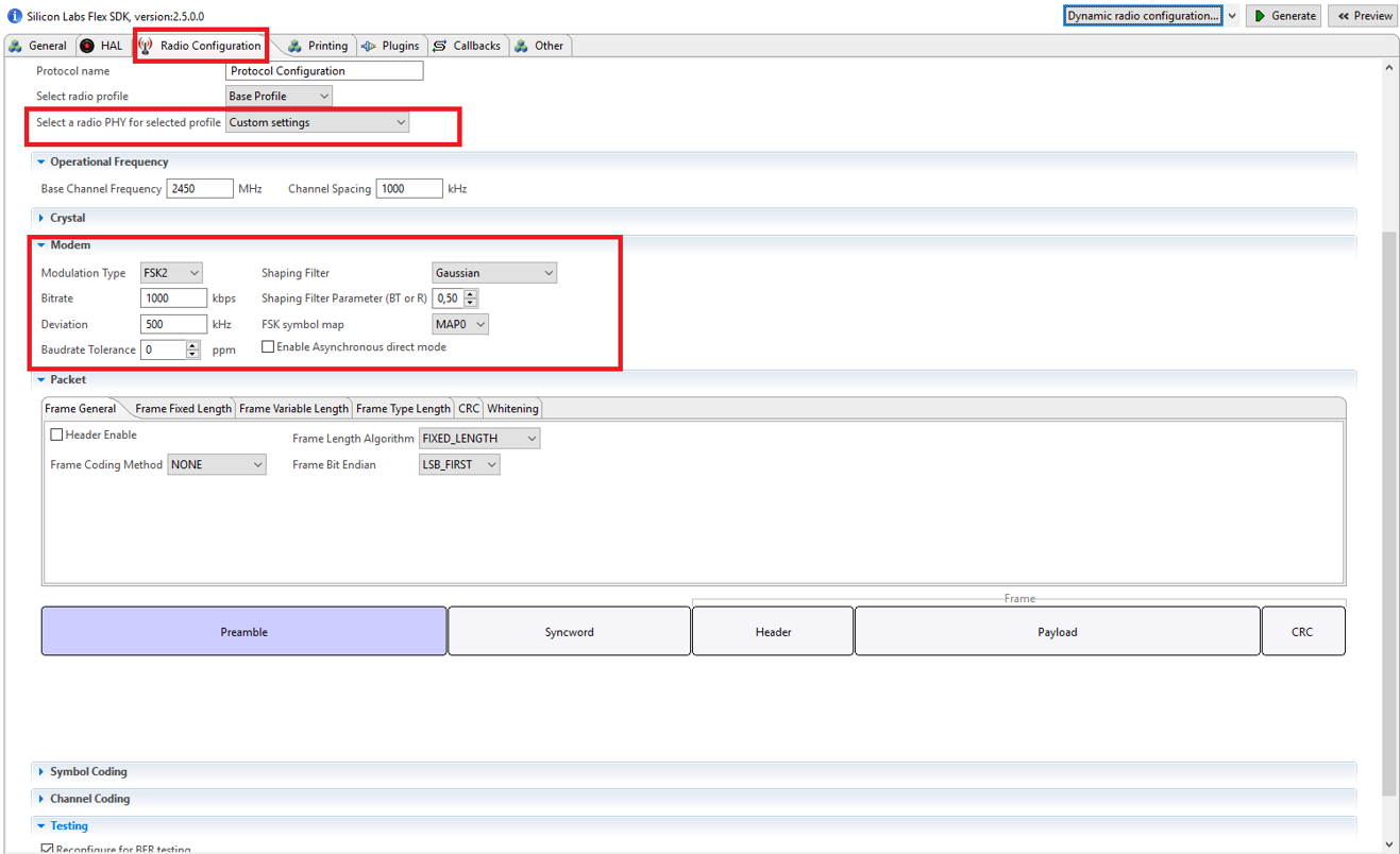
- Configure the radio parameters for example
- Modulation Type: FSK2
- Shaping Filter: Gaussian
- Shaping Filter Parameter: 0.5
- Bitrate [bps] / Deviation [Hz]: 125k/?, 500k/125k , 1M/250k, 2M/500k
- Modulation index: 0.5 based on BLE standard
- Checked the "Reconfigure for BER testing” box
- Everything else is default
- Generate
- Build

After build the Railtest tool, you can use the commander tool to program customer device, then the device will be ready for RF test. More information for Simplicity Studio usage, please visit the application note AN0822.
The frequency can be measured by a frequency counter or a Spectrum Analyzer (SA). The following strategy is proposed to determine the optimal Ctune value by using a SA:
- Performe a conducted measurement;
- Connect the custom board's RF port to a SA;
- Use SA to measure the fundamental frequency as following picture shows:

- Make sure to set appropriate span and Resolution Bandwitdth (RBW) on the spectrum analyzer. Use a few MHz frequency range as span and a few kHz as RBW.
- Tune the CTune value until the frequency of the fundamental harmonic reach the optimal value.
- Use RailTest tool to tune CTune. The RailTest commands are listed below:
- ->rx 0
- ->SetPower [decidBm]
- ->setdebugmode 1
- ->freqoverride 868000000
- ->GetCTune
- ->SetCTune 0x[hex-value] or [desimal value]
- ->SetTxtone 1
- ->SetTxtone 0
Railtest commands explanation:
- Railtest starts with "rx 0" command.
- The actual output power can be set by "SetPower" command.
- The actual output frequency can be set by "setdebugmode 1" and "freqoverride" commands.
- The actual CTune variable can be read by "GetCtune" command.
- It can set a new value to CTune, which can be done by "SetCTune" command.
- After the configuration, the "SetTxTone 1" command sets the radio to transmit mode. In this case the radio transmits CW signal.
- The CW transmission can be disabled by "SetTXtone 0" command.
For more Railtest commands information, please refer to this KBA.
For more CTune calibration details, it is discussed in this KBA.
The fundamental power and harmonics measurement are the basic test items for Tx performance. Usually the test will deploy a single tone signal at its maximum output power state, then the CW signal will be injected into a SA by a RF cable for the measurement. The RF cable should be attached to the 50 ohm point, and the antenna and its matching circuits should be removed from the RF cable attaching point. For generating the desire CW signal, it can use the Railtest tool to control the radio board to do that. As the Railtest tool is already generated in chapter 3, it can be used for this test directly.
The RailTest commands are listed below:
- ->rx 0
- ->Setchannel 0
- ->SetPower [max]
- ->SetTxtone 1
- ->SetTxtone 0
- ->setchannel 1
- ->SetTxtone 1
- ->SetTxtone 0
Railtest commands explanation:
- Railtest starts with "rx 0" command;
- Setchannel 0 will select a frequency points to test, it can also select another frequency point to test by changing the channel number;
- It can use SetPower [max] to set maximum output power;
- The "SetTxTone 1" command sets the radio to CW transmit mode, and the radio will transmit CW signal.
- The CW signal transmission can be disabled by "SetTXtone 0" command. Then the Setchannel command can be issued in idle radio state.
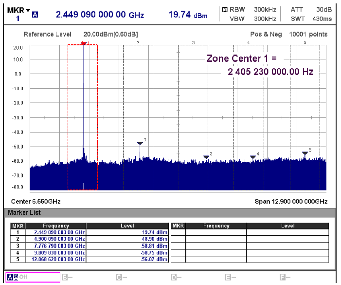
It is unlike CTune calibration, the fundamental and harmonics test requires big frequency span and big RBW for fast sweep measurement.
- Set appropriate reference level for the test, e.g. if your maximum output power is +20dBm, you can set reference level to +23dBm which is greater than maximum power by 2-3 dB;
- Set the frequency span to contain the fundamental and desired harmonics for the test. Usually 5 times fundamental frequency is desired. But according to the regulation, the maximum harmonic is tested at 10 times of fundamental;
- Set the RBW as big as possible, as long as the noise floor of SA should below the limit by 3 dB to 10dB.
- Set the VBW to 3 times of RBW;
- Set the trace mode to Max Hold;
- Set the detector mode to Peak detector;
- It can set the cable loss in fundamental and harmonics frequency points, this will count the cable loss in the display results;
- It can set a marker table to display the signal strenghth at fundamental and harmonics.
The following picture is a test example:
Sensitivity is basic test item for Rx performance. Usually it use a Signal Generator (SG) to generate a modulated signal and inject it into radio chip. Then the radio chip can demodulate the signal into data, the Railtest tool can use the data to count the BER. Once the BER critia is achieved, then the SG power level is called sensitivity.
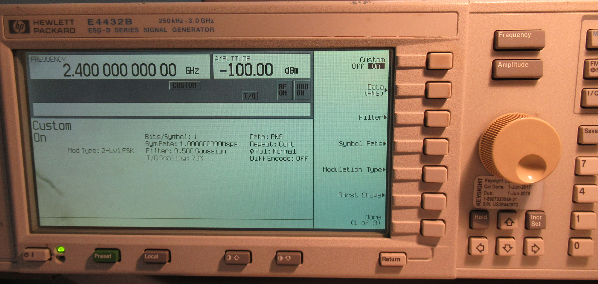
At beginning of the test, it should configure SA to generate right modulated signal. Following steps will configure a GFSK modulated signal:
- Set the SG to Custom Mode;
- Set IQ data to PN9;
- Set modulation type to 2-level FSK;
- Set filter to 0.5Bt Gaussian type;
- Set symble rate to the desired data rate, symble rate=data rate for 2GFSK modulation;
- Set frequency deviation to desired frequency deviation;
- Set frequency to desired operating frequency;
- RF: ON
- MOD: ON
- Tune signal strength level;
The RailTest commands are listed below for Rx BER test:
- ->rx 0
- ->Setchannel 0
- ->SetBerconfig 1000
- ->BerRx 1
- Wait a few seconds for desired bits receive complete;
- ->Berstatus
Railtest commands explaination:
- Railtest starts with "rx 0" command;
- Setchannel 0 will select a frequency points to test, it can also select another frequency point to test by changing the channel number;
- SetBerconfig 1000 sets 1000 bytes(8000 bits) data to count the BER;
- BerRx 1 sets the radio in BER RX mode;
- Wait for a while. Then the Berstatus command will display the BER test result.

When the PercentBitError rise up to 0.10, the SA's signal strength minus cable loss is the sensitivity under 0.1% BER.
Radiation test should be performed in an RF shielded anechoic chamber. Most of the regulation test items can be done with radiation test in an anechoic chamber. Besides that some antenna radiation parameter can be tested with radiation test such as TRP (Total Radiation Power), TIS (Total Isotropic Sensitivity), 2D cuts, and 3D pattern.
Generally there are 3 types of test site (environment) used to do radiation test:
- Open Area Test Site (OATS);
- Semi Anechoic Room (SAR);
- Fully Anechoic Room (FAR). They are referred to as free field test sites. Both absolute and relative measurements can be performed on these test sites. Most commonly used site is SAR for radiation test. The following picture shows the site configuration:

A Semi Anechoic Room is anechoic chamber with a conductive ground plane, and is an enclosure, usually shielded, whose internal walls and ceiling are covered with radio absorbing material. The floor, which is metallic, is not covered by absorbing material and forms the ground plane. The chamber usually contains an antenna mast at one end and a turntable at the other end. The antenna mast provides a variable height facility (from 1 m to 4 m) so that the position of the measurement antenna can be optimized for maximum coupled signal between the DUT and the measurement antenna. A turntable is capable of rotation through 360° in the horizontal plane and it is used to support the DUT at a specified height, usually 1,5 m above the ground plane. The measurement distance is standardized as 3m or 10m. The distance used in actual measurements shall be recorded with the test results.
Radiated measurements shall be performed with the aid of a measurement antenna and a substitution antenna described in the test site picture. The DUT and the measurement antenna shall be oriented such as to obtain the maximum emitted power level. This position shall be recorded in the measurement report:
- The measurement antenna (device 2 in following figure) shall be oriented initially for vertical polarization unless otherwise stated and the EUT (device 1 in following figure) shall be placed on the support in its standard position and switched on.
- The measurement equipment (device 3 in following figure) shall be connected to the measurement antenna and set-up according to the specifications of the test.

- The DUT shall be rotated through 360° in a horizontal plane until a maximum signal is received at the measurement equipment.
- The measurement antenna shall be raised or lowered again through the specified height range until a maximum is obtained at the measurement equipment. This level shall be recorded.
- This measurement shall be repeated for horizontal polarization.
Note: The measurement result is based on the test site. So it needs to calibate the test site before test.
 Home |
 ![]() Zigbee |
Zigbee | ![]() Bluetooth |
Bluetooth | ![]() ZWave |
ZWave | ![]() Proprietary |
Proprietary | ![]() Thread |
Thread | ![]() Matter |
Matter | ![]() Hardware |
Hardware | ![]() Common
Common
All resources of this repository are released under license CC BY-NC-ND 4.0 