2. Viewing and Manipulating Volumes with VVDViewer - JaneliaSciComp/VVDViewer GitHub Wiki
This page describes how to open files, manipulate rendered volumes, and optimize signal to noise ratio.
Opening Files
VVDViewer supports 3D and 4D datasets. You can load image slices (tif), image stacks (tif stack, nrrd, h5j, czi, lsm, oib, oif), meshes (obj, swc, ply) and chunked resolution pyramids (vvd, n5).
To open single files, do one of the following:
- Drag and drop files into the Workspace panel in the upper left corner of the window.
- Click "Open Volume, "Open Project", or "Open Mesh" on the Main Toolbar.

- Select "Open Volume", "Open Project", or "Open Mesh" from the drop-down File menu.
Opening Sequential Images
If you are opening a series of z-slices in an image stack or opening a time series, first make sure all files are in a single folder and the filenames end with sequential numbers, e.g. Image01.tif, Image02.tif, ... or “image_T0001.tif”, “image_T0002.tif”, ....
To load the images as a single volume:
- Select "Open Volume" from the Main Tool Bar or File menu
- Select the first image in the sequence
- Click the More Options button
- Select "Read a sequence as Z slices" or "Read a sequence as time series"
- Click Open.

You can also choose to compress data or remove blank images using the Additional Options dialog box.
4D date loading
- VVDViewer support multiple 4D file formats: .lsm, .nd2, .oib, and serial 3D tiff/zip files. For opening of 3D serial files, select only one first volume from the "Open Volume" dialog (do not select all 3D files).
Viewing Volumes
After you load a volume, all channels are shown in the Render View window. You can choose how to combine channels in the rendered volume and choose to view only a subset of channels.
Selecting Which Data Are Displayed in the Render View Window
You can hide or reveal different channels or groups by doing any of the following:
- Double-clicking on the lightbulb next to the item in the Workspace Panel
- Selecting the item and then clicking the eye icon on the Workspace Toolbar
- Selecting an item, clicking the left mouse button, and choosing Toggle Visibility from the drop-down menu.
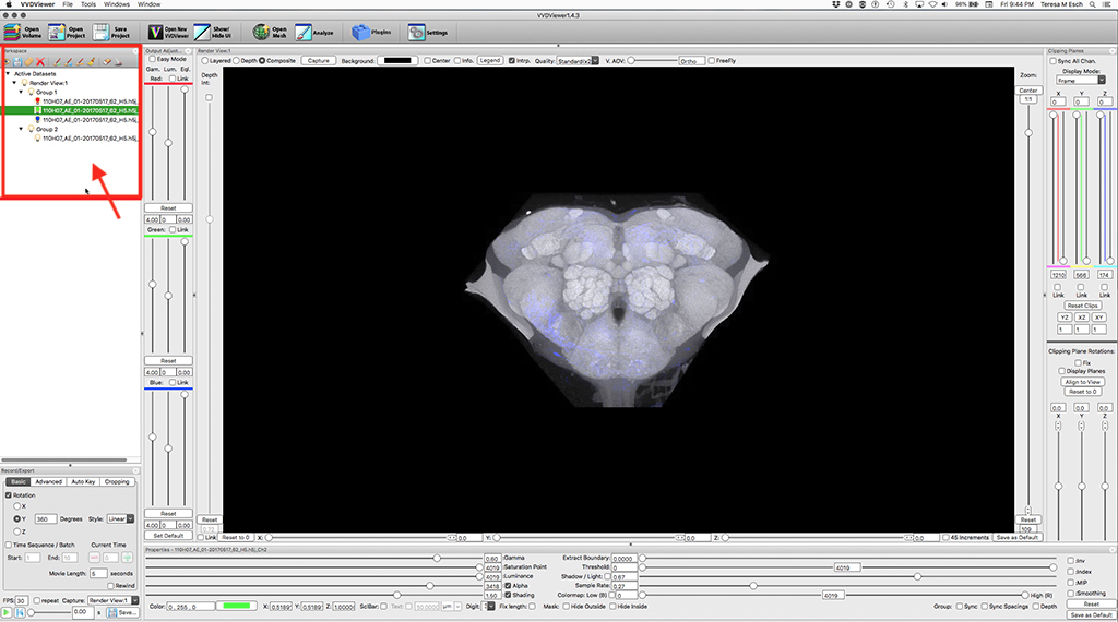
When the lightbulb is black, the channel/group is hidden. In the example below, only the red and blue channels of Group 1 are displayed in the Render View panel.

Choosing How Channels Are Combined in the Render View Window
Use the radio buttons at the top of the Render View panel to determine how channels are displayed. You can choose different modes for different groups of channels. For example, a group of 2 channels can be rendered in Composite mode, then layered on top of a second group.

- Layered: Channels are rendered individually and layered on top of each other. Thus, all portions of the top channel will be visible, even if they are deeper in the stack than portions of lower channels.The order of layers matches that in the Workspace panel. You can change the order by by dragging and dropping channels in the Workspace panel.
- Depth: All channels are rendered at once according to depth in the stack, so more superficial objects obscure deeper objects. Depth relationships are preserved.
- Composite: Channels are rendered individually and then blended. This allows deeper features to be seen.
Zooming In and Out
The percent zoom is shown in a box at the bottom of the Zoom slider.
You can zoom in and out on the image in the Render View window by doing any of the following:
- Using the slider on the right side of the Render View panel
- Holding down the right mouse button while dragging on the Render View window
- Using the mouse scroll wheel when cursor is on Render View window
- Typing a zoom amount in the box below the Zoom slider

You can set the current zoom level as the default by clicking "Save as Default" under the Zoom slider. You can then return to that zoom level by clicking the "Reset" button.
Rotating 3D Volumes
You can rotate the 3D image by doing any of the following:
- Holding down the left mouse button while dragging with the cursor positioned on the image
- Dragging or clicking a position on the X, Y, and Z sliders at the bottom of the Render View panel
- Typing numbers into the X, Y, and/or Z boxes at the bottom of the Render View panel

To rotate the image in 45-degree increments, select the 45 increments checkbox to the right of the rotation sliders.
To return to the original position, click Reset to 0 to the left of the rotation sliders.
To see the center of rotation on the rendered image, click the Center checkbox at the top of the Render View panel. This is helpful when creating movies, but it should be unchecked if you don't want it to appear on a captured image or movie.

Repositioning Images
- To drag the image in the Render View window, hold down the Command key and left mouse button while dragging the cursor on the window.
Displaying Signal Intensity as Color Map
- When the Colormap box in the Properties panel is checked, signal intensity is indicated with color heat map. Sliders allow you to adjust the color range.
Fly-Through Mode
- When the FreeFly checkbox at the top of the Render View panel is checked, the image appears as if the camera is inside your sample. The user can check the 3D object from inside.

Optimizing the Appearance of the Rendered Volume
When you load volume data for the first time, you will likely want to adjust brightness and contrast to make fine structures discernible from background fluorescence. This is done on a channel-by-channel basis. Select a channel to manipulate using the Workspace Panel, then make adjustments to brightness and contrast using the Output Adjustment and Properties panels, as described below.
Changing the Color of a Channel
- When you select a channel in the Workspace panel, the color assigned to the channel appears in the Color box at the bottom of the Properties panel.

There are three ways to change the color assigned to the channel:
• Enter values (0-255) for R, G, and B (e.g., "255, 0, 0" for red)
• Select all three numbers and replace with "w" for white, "p" for purple, "r" for red, "g" for green, or "b" for blue
• Double-click on the color bar to select a color from the color-picker window
Note, the 2D parameter values for Red, Blue, and Green are shared among all channels in a group. Therefore, if two or more channels use the same color component (e.g., orange and purple both have a red component) the same parameters will be used for that color component in multiple channels. If you want to use different 2D parameters for the two channels, create a new group in the Workspace panel by dragging and dropping one channel outside the group. Then, in this example, the red settings for the purple channel can be set differently than the red settings for orange channel.
Adjusting 2D Image Brightness and Contrast
- 2D brightness and contrast adjustments are made in the Output Adjustment panel. The parameters can be set independently for each color (RGB), but if the Link checkbox is selected, each parameter is set to the same value for all colors. The Link checkbox is automatically selected if the channel uses a combination of Red, Green, and Blue (e.g., a purple channel will have blue and red components, so the Link checkboxes for Red and Blue will be checked when this channel is selected in the Workspace Panel).

Select Easy Mode to adjust brightness and contrast at once. Deselecting Easy Mode allows you to adjust gamma, luminosity, and equalization individually.
-
Gamma(Gam): uses a Gamma curve to adjust color intensity (brightness). This allows you to increase the visibility of dimmer signals without oversaturating brighter signals.
-
Luminosity (Lum): uses a multiplier to adjust color intensity, thus increasing the brightness of all signals.
-
Equalization (Eql): also makes dimmer signals brighter. It is most useful for equalizing brightness across time points in 4D data sets; it is less useful than Gam/Lum in most other cases.
Adjusting 3D Channel Properties
- After selecting a channel in the Workspace panel and making initial adjustments in the Output Adjustment panel, you can further enhance signal and reduce background by adjusting parameters in the Properties panel.
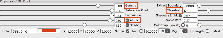
The most useful tools for bringing out signal to background are the following:
-
Gamma: Brightens dimmer signals without saturating already bright signals
-
Alpha: adjusts transparency. This is useful for reducing background fluorescence
-
Threshold: Left slider clips signals below the set value, e.g. to hide background fluorescence. Right slider clips signals above the set value.
Additional parameters that can be used to adjust the appearance of the rendered volume include:
-
Saturation Point: Sets all intensity values greater than the set value the highest intensity.
-
Luminance: adjusts the brightness of all signals
-
Shading: enhances 3D appearance by adding a shading effect
-
Shadow / Light: When the box is checked, this slider enhances the 3D effect
-
Smoothing: Applies a saddle smoothing filter. This filter is good for deleting voxel lattice pattern from the 0 degree rendering
-
Extract Boundary: This function is good for adjusting the brightness of background tissue so it doesn't obscure internal signals (e.g., labeled cells)
The Depth Attenuation: visualization enhancement of 3D depth
- To make deeper signals appear darker in the Render View window, use the Depth Attenuation Slider located on the left side. You can turn depth attenuation on and off by clicking the checkbox above the slider. Adjust the slider to increase or decrease the amount of depth attenuation.

Smoothing
- Checking the "Intrp" box in the Render View Settings panel will make the image smoother using a technique called trilinear interpolation. While leaving it unchecked will preserve the original, more pixelated appearance.
Viewing Smaller Sections of a Rendered Volume
- Clipping planes allow you to see small sections of your rendered volume. This is useful when a more superficial structure is occluding deeper structures in thick stacks. It also lets you scroll through individual slices of a z-stack and can facilitate segmentation of objects.

To view clipping planes, place the mouse cursor over the Clipping Planes panel. To keep the planes visible when you move the cursor off the panel, select the Display Planes checkbox in the Clipping Planes panel.

There are several ways to adjust the position of clipping planes depending on your objective:
To hone in on or crop out a particular object, drag the X, Y, and Z sliders to move the planes to the desired position. Objects outside the clipping planes are occluded from view.
To place clipping planes at a particular place in the stack, type numbers into the boxes above and below the sliders. Note, before clipping planes are set, the numbers below the sliders show the total number of voxels in the X and Y dimensions and the number of slices in the Z stack.
Example: If the Z+ slider is set to 10 and the Z- slider is set to 20, only slices 11-20 of the image stack will be shown in the Render View window.
To use the same clipping plane settings for all channels, click the Sync All Chan. box at the top of the Clipping Planes panel
To view the entire volume again, click the Reset Clips button.
Scrolling Through a Z-Stack
-
When the Link checkbox below the X, Y, or Z slider is selected, dragging the associated slider moves the two opposite clipping planes at the same time, keeping the distance between them the same. This allows you to easily scroll through the volume.
-
You can show a single Z slice either by typing "0" in the box above the Z slider and typing "1 in the box below the slider, or by typing "1" in the box under the XY button, then clicking that button. When you do the latter, the Link box will automatically be checked. You can then use the sliders to scroll through the stack.
Rotating Clipping Planes
- Rotating the clipping planes is useful when a scan is tilted at an angle.
The group of six clipping planes can be rotated independently of the selected volume channel. There are two methods for clipping plane rotations. To directly adjust clipping plane rotations, change the rotation values using sliders or numeric boxes. To rotate clipping planes using rotation controls in the Render View panel, first rotate the view to an angle, so that the user is looking straight at a desired XY plane. Then, click “Align to View” to rotate clipping planes to align with the intended XY plane. Fix: When this box is checked, the clipping planes remain in the same place in the Render View panel. Then you can see different cross sections of the rendered volume by rotating or translating the object in the Render View panel.