esp8266blink - JamesNewton/JamesNewton.github.io GitHub Wiki
2019/03/09 San Diego CoLab
Learn to program an Arduino compatible ESP-8266 micro-controller to blink a light with any pattern you can imagine. And... CONTROL THE WORLD!!! No really, because if you can blink a light, you can tape the unit with it's LED in front of a light or motion activated outlet to control anything you can plug in. Pump? Fan? Light?. Doomsday machine! In the next class, we will learn how to make things move with RC Servos.
What you need:
- A PC with a USB port and micro B cable, web browser / internet, and the Arduino IDE from
www.arduino.cc
click "Software", "Downloads", scroll down and download / install. - How to work with files, create a folder, Copy and Paste Files, etc...
- Basic text editing, like copying and pasting text, etc...
- A very solid understanding that YOU are perfectly capable, and all the weird problems you run into are caused by poorly written programs, bad cables, and other random junk.
NodeMCU v1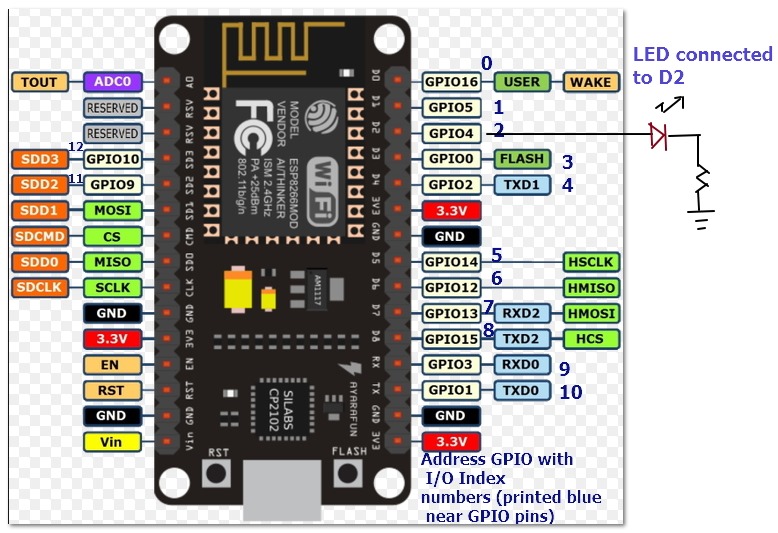 |
USB A to micro B cable (short)
^ ^ |
Our world today depends on Microcontrollers like the Arduino, from iPods to Power Stations, Laptops to Defibrillator Paddles. Arduinos control most 3D printers, Quadcopters, and much more!
But how do they work? How can you use them? Can you make stuff light up, blink, throb, move, and come to life? YES! Because Arduinos can be very fun. And each part of it is easy.
This class will cover the basics, teach you to program a low cost but amazingly powerful Arduino clone, and provide you with some options for learning and doing more.
Arduino is a family of little electronic brains, starting with the UNO back in 2005, to give students an inexpensive and easy way to program. It's an open-source design with USB programming, and lots of pins for input and output (IO): digital, analog, and PWM / RC servo. A simple integrated development environment (IDE) supports C or C++ code for all the versions.
Versions are available for $5 to $80 dollars pre-assembled or as kits. You can also make your own.
http://www.instructables.com/id/20-Unbelievable-Arduino-Projects/
The ESP-8266 is a closed source device that was never intended to be an Arduino programmable unit. Hackers reverse engineered it and found a way to make it work. It not only has all the standard Arduino IO stuff, but it also has WiFi! As it, it can connect to WiFi, it can provide WiFi... it can even serve web pages!
Yeah, it's a Web Server for $5.
But it doesn't have a USB connector. So the ESP-8266 "ESP-12" version was added to an open source PCB called "NodeMCU" which adds on the USB connector, and LED, and a few other cool things; makes it easy for us to work with it.
For (a lot) more, see:
http://techref.massmind.org/techref/esp-8266.htm
 Download the 1.8.x version of the IDE (Integrated Development Environment) from:
https://www.arduino.cc/en/software#legacy-ide-18x Scroll down to "Legacy IDE (1.8.X)".
And install it on your PC. We can't use the 2.0 version because it no longer supports download of files into the onboard file system.
Once it's installed, start it, and update the boards:
-
Click
File,Preferencesand go toAdditional Board Manager URLs -
Copy in:
http://arduino.esp8266.com/stable/package_esp8266com_index.json
- Click
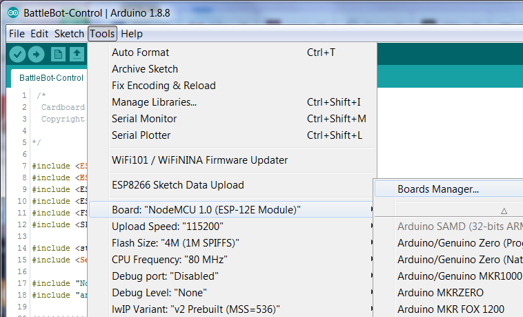
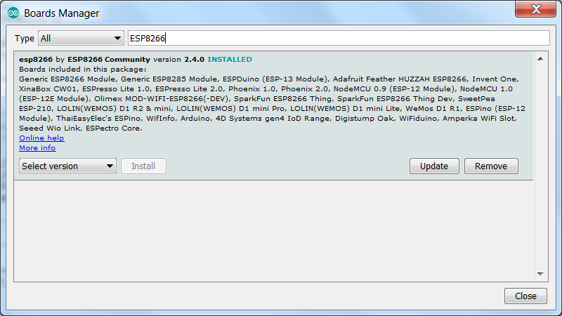
Tools,Board: (whatever)andBoards Manager. Let it load, then search for "esp8266", click it and install it.
Click Tools, Board: (whatever) again and change it to NodeMCU 1.0 (ESP-12E Module
Set the Upload Speed: to 115200
The Port: should be greyed out, or it should show something that isn't right, since we haven't connected the device.
The rest should default correctly. Check that it looks like this:
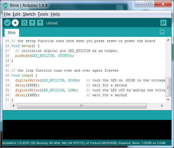
Click File / Examples / 01.Basics / Blink
Scroll down to the bottom:
// the setup function runs once when you press reset or power the board
void setup() {
  // initialize digital pin LED_BUILTIN as an output.
  pinMode(LED_BUILTIN, OUTPUT);
}

// the loop function runs over and over again forever
void loop() {
  digitalWrite(LED_BUILTIN, HIGH);   // turn the LED on (HIGH is the voltage level)
  delay(1000);                       // wait for a second
  digitalWrite(LED_BUILTIN, LOW);    // turn the LED off by making the voltage LOW
  delay(1000);                       // wait for a second
}
Try reading through that and guess what it will do. Hint: The delay is expressed in 1/1000 of a second.
Plug in the NodeMCU via the USB cable to your computer. Wait for a while to make sure the computer see's the unit and installs the driver for it. That should happen automatically.
Now check the Tools menu to see if the Port: setting has changed. The new port is your NodeMCU so select that if it isn't already. If it doesn't show up, please ask for help.
Click Sketch / Upload or press Ctrl+U or click the Arrow icon next to the Check icon at the top of the editor window.
CHALLENGE!
Edit the program to blink out SOS. That is three short blinks, three long blinks, and then three short again.
Hint: Copy and paste the lines inside the loop, then change the delay numbers to make a long blink and a short blink.
Change the loop() so it looks like this: (copy from here, paste in)
#define HIGHEST 1023 //on ESP, 1023 is max for analogWrite (not 255)
#define LOWEST 0
void loop() { //arduino.cc/en/Reference/For
 for (int i=LOWEST; i<HIGHEST+1; i++) { //i will go from low to high
   analogWrite(LED_BUILTIN, i);  // PWM out the current value of i
   delay(2); //notice how short the delay is? 2*1023=2046
   } //do it HIGHEST - LOWEST times.
 for (int i=HIGHEST; i>=LOWEST; i--) { //Back down again
   analogWrite(LED_BUILTIN, i);  // PWM back down
   delay(2);
   }
 }
Learn more about "for" in "Flow Control Statements" or
http://arduino.cc/en/Reference/For or http://jsbin.com/lesasidu/1/edit
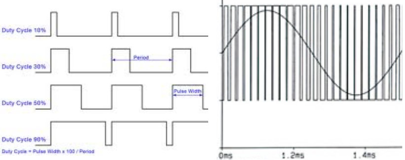
So analogWrite is actually putting out digital signals: Fully on or fully off. But it's switching between on and off so fast that a) you can't see it b) the light looks partly off (or partly on). Using this fast Pulse Width Modulation, or PWM, we can "fake" any analog signal. *
CHALLENGE!
Edit the program to pulse twice, pause, and repeat. Like a heartbeat.
Hint: Add a delay at the end. You could just copy the 2 for loops and paste them in twice, but you could also just add a big for loop around all of it, and use a different index (like "j" instead of "i").
Note: PWM is also used to control RC servos; their position is controlled by the duty cycle. Actually, it's PPM (Pulse Position Modulation) but the difference is slight: Only the one time matters, not the percentage, and they use a slower frequency, 50Hz. On the ESP, we can actually change the PWM frequency with analogWriteFreq(new_frequency). But there is a better system, which we will learn in the next lesson.
- Mismatched {}, [], (). If you put your cursor on one, the matching one will be highlighted. Did the highlight show up were it should?
- Slight spelling or typing errors. A single missing
;will mess everything up, make sure every line, except for empty lines or those that end with { or } have a;. Correctly spelled stuff will highlight. e.g.
void test();
v0id test();- Silly stuff. Unit's not plugged in all the way, cable defective, wrong device selected on Tools / Board:, wrong port, phase of the moon, techo-gods need a small appliance sacrificed to them.